

Three-phase mains
The L1/L2/L3 terminals accept 324...528 V rms. Protective earth and the selected branch-circuit device complete the incoming power boundary.
Welcome to Moore Automation Limited



|
Copy and share this link on social network or send it to your friends
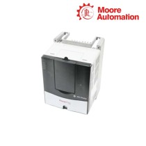
Copy| Product Name | Allen-Bradley 2094-BC01-MP5-S Kinetix 6000 Integrated Axis Module |
| Item NO. | 2913157 |
| Weight | 0.1 kg = 0.2205 lb = 3.5274 oz |
| Category | AB |
| Brand | ALLEN-BRADLEY |
| Creation Time | 2026-10-07 |
The Allen-Bradley 2094-BC01-MP5-S is a Kinetix 6000 integrated axis module that combines the 400/460 V-class converter and one servo inverter on the left end of a Bulletin 2094 power rail. Three-phase line power enters the converter, becomes the shared DC-bus supply for the rail, and also feeds the module’s own 4.0 A peak axis channel for closed-loop motor control.
Within the power and control path, 2094-BC01-MP5-S accepts 95...264 V single-phase control power separately from its 324...528 V three-phase main input. Motor power leaves through U/V/W, motor feedback returns through the dedicated feedback interface, SERCOS carries the motion command and status stream, and the nine-pin safe torque-off connector controls the torque-producing gate signals without being used as a normal start/stop command.
| Technical Item | 2094-BC01-MP5-S |
|---|---|
| Brand | Allen-Bradley |
| Product Type | Kinetix 6000 integrated axis module |
| Country of Origin | Mexico |
| Main AC Input | 324...528 V rms, three-phase (360...480 V nominal) |
| Control Power Input | 95...264 V rms, single-phase (110...240 V nominal) |
| DC Input as Common-bus Follower | 458...747 V DC |
| Converter Continuous Bus Current | 9.0 A DC |
| Converter Continuous Bus Power | 6 kW |
| Inverter Nominal DC Input | 650 V DC |
| Inverter Continuous Output Current | 2.8 A rms / 4.0 A sine 0-peak |
| Inverter Continuous Output Power | 1.8 kW |
| Safe Torque-Off Response Time | 25 ms typical |
| Short-circuit Current Rating | 200,000 A rms symmetrical |
| Operating Ambient | 0...50 °C (32...122 °F) |
| Approximate Weight | 4.98 kg (11.0 lb) |
| IAM Dimension References A / B / D / E / F | 272 / 249 / 0 / 256 / 287 mm |
| Enclosure Requirement for Safety Rating | Protected control panel or cabinet, IP54 or higher |
The L1/L2/L3 terminals accept 324...528 V rms. Protective earth and the selected branch-circuit device complete the incoming power boundary.
The converter delivers 9.0 A continuously to the shared DC bus. A follower configuration can instead receive 458...747 V DC through the bus terminals.
Axis modules to the right draw from the common rail. Their highest average power utilization is placed nearest the integrated axis module.
The local inverter operates from a nominal 650 V DC bus and supplies 2.8 A rms continuous, or 4.0 A sine 0-peak, to its motor channel.
The safe torque-off interface on 2094-BC01-MP5-S uses redundant enable inputs and feedback contacts so the external safety circuit can request torque removal and verify the drive-side state.
ENABLE1 and ENABLE2 form separate channels. Both must be valid for the power stage to receive torque-producing gate commands.
FDBK1 and FDBK2 provide the external safety logic with two status paths instead of treating a single command signal as proof of the safe state.
The typical time from an STO input state change to the corresponding drive-output state change is 25 ms; total machine stopping time remains application-dependent.
Maintaining the published safety rating requires the drive to be installed in a protected control panel or cabinet with IP54 or higher protection.

Network communication does not override the safe torque-off circuit. Check both safety-enable channels, the 24 V safety supply, the installed STO header and normal drive-enable conditions before tracing the motor output.
The published continuous and peak current ratings are reduced for constant-velocity operation below 5 Hz, equivalent to 75 rpm on an eight-pole motor. Use the low-speed duty when sizing the axis instead of applying the high-speed current rating unchanged.
The 360...480 V input table identifies a 20 A Class CC KTK-R-20 fuse for UL applications, with other listed protection options depending on the installation standard. Control-power and main-input protection are separate selections and must follow the installed circuit.
The integrated axis module occupies the leftmost rail slot. Higher-utilization axis modules follow to its right, the shunt follows the last axis or IPIM module, and every unused connector requires a 2094-PRF slot filler.
Series A or B modules mixed with Series C modules require the same firmware revision, version 1.125 or later, across the affected drive modules. Safe-off commissioning also requires firmware revision 1.88 or later.
Rockwell Automation identifies 2198-D012-ERS3 as an engineering replacement, not a direct drop-in exchange. Review controller architecture, network, safety circuit, motor and feedback compatibility, power design, mounting and project configuration before migration.

Moore Automation supports industrial control, motion, safety and monitoring spare-parts enquiries with complete catalog-number checking and one accountable contact from quotation through dispatch.



Moore Automation Sales Team
Copyright © 2004–2026 www.mvme.cn. All rights reserved.
Disclaimer: Moore Automation Limited is an independent reseller and is not an authorized distributor or representative of the manufacturers featured on this website. Product names and trademarks belong to their respective owners.
No related record found