

IAM first
The integrated converter occupies the dedicated leftmost position and precharges the rail before any axis module can produce motor output.
Welcome to Moore Automation Limited




|
Copy and share this link on social network or send it to your friends
Copy| Product Name | Allen-Bradley 2094-AC09-M02-S / 2094-AC16-M03-S Kinetix 6000 230V IAM Power Modules |
| Item NO. | 2913751 |
| Weight | 0.1 kg = 0.2205 lb = 3.5274 oz |
| Category | AB |
| Brand | ALLEN-BRADLEY |
| Creation Time | 2026-10-09 |
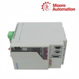
For mid-range 230 V multi-axis systems, the Allen-Bradley 2094-AC09-M02-S / 2094-AC16-M03-S are Kinetix 6000 integrated axis modules that create the rail DC bus and control the first servo axis. Their SERCOS control loop carries cyclic motion commands through fiber, while dedicated motor-power and feedback connectors close the electrical loop at the physical axis.
During rail assembly, 2094-AC09-M02-S / 2094-AC16-M03-S remain at the left edge and are followed by axis modules ordered from the highest power utilization downward. Choosing between the M02 and M03 power stages changes converter headroom, motor-output current and frame width, so rail population and enclosure clearance are resolved with the exact IAM rather than the family name.
| Technical Item | 2094-AC09-M02-S | 2094-AC16-M03-S |
|---|---|---|
| Brand | Allen-Bradley | |
| Product Type | Integrated axis power module | |
| Series | Kinetix 6000 | |
| AC Input Voltage | 195…264 V rms, three-phase | |
| AC Input Frequency | 47…63 Hz | |
| Control Power Input | 95…264 V rms, single-phase | |
| Nominal DC Bus | 325 V DC | |
| Converter Output Power | 6.0 kW | 11.3 kW |
| Continuous Output Current | 10.6 A rms | 17.3 A rms |
| Continuous Output Current, 0-pk | 15.0 A | 24.5 A |
| Peak Output Current | 21.2 A rms | 34.6 A rms |
| Peak Output Current, 0-pk | 30.0 A | 48.9 A |
| Continuous Output Power | 3.4 kW | 5.5 kW |
| PWM Frequency | 8 kHz | 4 kHz |
| Bus Capacitance | 780 µF | 1320 µF |
| Capacitive Energy Absorption | 29 J | 50 J |
| Efficiency | 98% | |
| Short-Circuit Current Rating | 200,000 A rms symmetrical | |
| Approximate Weight | 2.31 kg | 4.71 kg |
| Dimensions A / B / Width / E / F | 198 / 176 / 51 / 206 / 237 mm | 198 / 176 / 125 / 302 / 420 mm |
The Allen-Bradley 2094-AC09-M02-S / 2094-AC16-M03-S feed every downstream axis through the power rail, making physical order part of the current-distribution design.
The integrated converter occupies the dedicated leftmost position and precharges the rail before any axis module can produce motor output.
The axis module with the greatest percentage of its rated power is placed closest to the IAM, followed by progressively lower-utilization axes.
A rail-mounted shunt module follows the active axis group in the location assigned to its connector and thermal-clearance requirements.
Slot fillers close any remaining rail connectors after all active modules have been installed in their calculated order.
The Allen-Bradley 2094-AC09-M02-S / 2094-AC16-M03-S exchange cyclic axis data through SERCOS receive and transmit ports while power and feedback use separate wiring.
The incoming fiber carries controller telegrams to the IAM node without sharing conductors with the 230 V supply or motor cable.
The outgoing port continues the optical ring to the next drive, so an open connector interrupts devices farther around the loop.
The drive address identifies this IAM in the controller project and must remain unique within the configured SERCOS ring.
Module indicators expose ring and axis status locally, allowing a link fault to be separated from a motor-power or feedback problem.
On 2094-AC09-M02-S / 2094-AC16-M03-S, the AC16/M03 combination provides more converter and inverter capacity and uses a wider frame. Select from total rail demand and the first motor axis, not from the catalog sequence alone.
Before wiring 2094-AC09-M02-S / 2094-AC16-M03-S, rail current passes outward from the IAM. Placing the most heavily utilized modules nearest it reduces the current carried through downstream rail sections.
While commissioning 2094-AC09-M02-S / 2094-AC16-M03-S, the controller can no longer complete normal optical communication through that point. Inspect both receive and transmit paths, connector seating and the configured node address.
No. For 2094-AC09-M02-S / 2094-AC16-M03-S, the precharge circuit needs the specified recovery interval between power cycles. Use axis commands and safe-off functions for normal control instead of cycling mains power.
No. Within a 2094-AC09-M02-S / 2094-AC16-M03-S installation, the shunt absorbs regenerated DC-bus energy, while the motor brake is a separate holding device controlled through its own circuit. Their wiring and functions are not interchangeable.
When specifying 2094-AC09-M02-S / 2094-AC16-M03-S, plan from the complete frame and cable-clearance dimensions. Leave airflow and bend room above and below the terminals as well as side clearance for adjacent modules.
Moore Automation supports enquiries with model clarification, document coordination, quotation follow-up and shipment communication. Sharing the complete manufacturer catalog number and quantity at the start lets the sales team keep each request traceable through the response.
Send the complete model and requested quantity.




Moore Automation Sales Team
Copyright © 2004–2026 www.mvme.cn. All rights reserved.
Disclaimer: Moore Automation Limited is an independent reseller and is not an authorized distributor or representative of the manufacturers featured on this website. Product names and trademarks belong to their respective owners.
No related record found