

Excitation and measurement
The module supplies a controlled measurement current, reads the resistance-dependent voltage and converts the result using the configured RTD or potentiometer curve.
Welcome to Moore Automation Limited




|
Copy and share this link on social network or send it to your friends
Copy| Product Name | Yokogawa ASR133-S00 S1 | 8-Channel RTD/POT Input Module with Built-In Barrier |
| Item NO. | 2929203 |
| Weight | 0.1 kg = 0.2205 lb = 3.5274 oz |
| Category | YOKOGAWA |
| Brand | YOKOGAWA |
| Creation Time | 2026-11-02 |
YOKOGAWA · CENTUM ENGINEERING RECORD
Yokogawa ASR133-S00 S1 is an eight-channel isolated RTD and potentiometer input module with built-in barriers for CENTUM field I/O. It accepts 2-, 3- or 4-wire resistance thermometers from the supported platinum and nickel families, or 3-wire potentiometers up to 10 kΩ.
A 150 µA measurement current from Yokogawa ASR133-S00 S1 passes through the selected sensor circuit and the module converts the resulting resistance into controller data. Lead arrangement matters: 3-wire and 4-wire terminations use separate conductor paths to distinguish sensor resistance from wiring resistance.
Through the ATSR3 pressure-clamp terminal, Yokogawa ASR133-S00 S1 keeps each sensor channel isolated while using the terminal map appropriate to 2-, 3- or 4-wire service. Equal lead resistance is required where the measurement method depends on lead compensation.

| TECHNICAL ITEM |
|
|---|---|
| Brand | Yokogawa |
| Model | ASR133-S00 S1 |
| Nameplate Suffix | S1 |
| Product Name | RTD/POT input module with built-in barrier |
| Country | Japan |
| Input Channels | 8 isolated |
| RTD Wiring | 2-, 3- and 4-wire |
| RTD Families | Pt50, Pt100, Pt200, Pt500, Pt1000; Ni100, Ni200, Ni120 |
| Potentiometer | 3-wire, 0 to 10 kΩ |
| Channel Selection | RTD or POT individually for CH1 to CH8 |
| Allowable Input | ±5 V |
| Input Resistance | 1 MΩ or greater |
| Measurement Current | 150 µA |
| Lead Resistance | 50 Ω per lead maximum; equal leads required |
| Update Period | 1 second or less |
| Burn-out | Module-wide enable/disable; UP or DOWN |
| External Terminal | ATSR3 pressure clamp terminal |
| Barrier Type | Isolated interface |
| Current Consumption | 150 mA at 5 V plus 60 mA at 24 V |
| Dimensions | 32.8 × 130 × 107.5 mm |
| Weight | Approx. 0.30 kg |
ASR133-S00 S1 converts several resistance-sensor families into process values while preserving per-channel isolation.
The module supplies a controlled measurement current, reads the resistance-dependent voltage and converts the result using the configured RTD or potentiometer curve.
Three- and four-wire arrangements separate lead effects from the sensor element; equal conductor resistance is essential where the selected method assumes balanced leads.
The module-wide burn-out setting sends failed channels UP or DOWN, giving the control strategy a defined response to open sensor wiring.
ASR133-S00 S1 installation starts with an exact sensor and lead-count schedule rather than a generic resistance-input wiring plan.
Confirm the RTD standard or potentiometer range for every channel, then select the 2-, 3- or 4-wire terminal pattern shown for the ATSR3 block.
Keep lead materials, cross-sections and routing consistent; connect each conductor to the assigned input terminal without borrowing a return from another channel.
After power-up, compare representative channels with a known resistance source, verify the engineering conversion and test the configured burn-out direction by opening the circuit under the approved procedure.
Yokogawa ASR133-S00 S1 accepts the documented Pt and Ni RTD families in 2-, 3- or 4-wire form, plus 3-wire potentiometers from 0 to 10 kΩ.
Yokogawa ASR133-S00 S1 relies on the selected wiring method to separate lead resistance from the sensor value; unequal or excessive leads produce measurement error.
No. Yokogawa ASR133-S00 S1 uses isolated channel terminal patterns, and each sensor must retain the complete documented conductor set for its selected 2-, 3- or 4-wire method.
Yokogawa ASR133-S00 S1 uses the ATSR3 pressure-clamp terminal family; choose the single or dual-redundant execution that matches the installed module arrangement.
For Yokogawa ASR133-S00 S1, connect a known precision resistance through the intended lead configuration, confirm the engineering value, then repeat at another point in the range.
Yokogawa ASR133-S00 S1 uses the configured module-wide burn-out direction; inspect the open wiring and confirm whether UP or DOWN is correct for the control strategy.
Moore Automation can record discontinued or difficult-to-source industrial part numbers alongside photographs, revision details and destination requirements. Any availability statement is confirmed for the individual enquiry rather than presented as guaranteed stock.

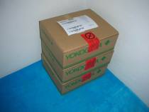
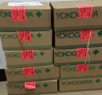
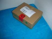
Moore Automation Sales Team
Copyright © 2004–2026 www.mvme.cn. All rights reserved.
Disclaimer: Moore Automation Limited is an independent reseller and is not an authorized distributor or representative of the manufacturers featured on this website. Product names and trademarks belong to their respective owners.
No related record found