




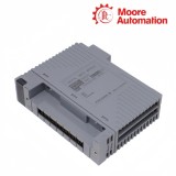

Yokogawa ADV169-PK0 RIO Upgrade Digital Input Module
Product Summary
Yokogawa ADV169-PK0 is a connector-type digital input module for upgrading an ADM12C position in a Yokogawa RIO system. Its main responsibility is to convert up to 32 active contact or voltage states into controller input data through the ST6-compatible upgrade hardware.
Inputs on Yokogawa ADV169-PK0 are arranged in two 16-channel groups with isolation organized on the minus side of each group. Status inputs use an 8 ms response, while the pushbutton function recognizes an ON interval of at least 20 ms within an ON/OFF period of 40 ms or longer.
Yokogawa ADV169-PK0 connects the legacy field connector through a KS9 or KS10 cable. The cable position establishes the relationship between the original ADM12C point numbers and the 32 active controller channels; the remaining positions of the 64-channel hardware family are not active in the PK upgrade configuration.
Technical Details
| Brand | Yokogawa |
|---|---|
| Model | ADV169-PK0 |
| Product Name | RIO Upgrade Digital Input Module |
| Country | Japan (manufacturer) |
| Hardware Family | 64-channel compatible ST6 input module |
| Active Upgrade Inputs | 32 for ADM12C upgrade |
| Input Types | Contact or voltage input |
| Contact OFF / ON | 100 kilohms or more / 200 ohms or lower |
| Voltage OFF / ON | 4.5 to 25 V DC / ±1 V DC |
| Input Response | 8 ms for status input |
| Pushbutton Detection | 20 ms minimum ON time |
| Pushbutton Period | 40 ms minimum ON/OFF period |
| Current Consumption | 170 mA at 24 V DC |
| Signal Connection | KS9 or KS10 cable |
| Net Weight | Approx. 0.56 kg |
ADM12C Upgrade Mapping
ADV169-PK0 is an upgrade module, so success depends on a controlled translation from the legacy ADM12C connector and point list to the 32 active inputs.
Freeze the old point list
Export or photograph the ADM12C channel assignment, cable identity and controller references before removal.
Mark unused and reserved points explicitly so the new ADV169-PK0 map does not shift later signals into open positions.
Respect the 32-input limit
Do not plan around the 64-channel family description. The PK upgrade configuration deliberately limits active inputs to thirty-two.
Verify the engineering database and I/O test sheet against that upgrade limit before energizing the node.
Retain the KS connection type
ADV169-PK0 uses KS9 or KS10 cable for the ADM12C connector route. Check cable code, connector condition and strain relief rather than substituting a terminal-type PM configuration.
A connector offset can affect a block of channels and should be investigated before individual points are blamed.
Status and Pushbutton Input Handling
ADV169-PK0 supports steady status detection and pushbutton edge counting, which require different timing expectations during tests.
Test steady states first
Apply defined OFF and ON resistance or voltage conditions and verify the 8 ms status-input response through the controller.
Check each sixteen-channel common group for reference continuity when a whole bank behaves incorrectly.
Generate valid pushbutton pulses
Hold the ON state for at least 20 ms and keep the full ON/OFF period at 40 ms or longer when testing edge counting.
Shorter pulses may be physically present but fall outside the documented detection conditions.
Separate wiring from logic
Use a meter at the connector and controller diagnostics together. A correct field state with no logical change points toward mapping or configuration; an incorrect connector state points toward wiring.
Record both observations for every migrated critical input.
Customer Questions
01Why does ADV169-PK0 expose only 32 inputs when the family is called 64-channel?+
ADV169-PK0 is the ADM12C RIO upgrade configuration, and Yokogawa limits the active input count to 32 for this K connection type.
02Why can ADV169-PK0 miss a short pushbutton action?+
ADV169-PK0 requires at least 20 ms ON time and a 40 ms minimum ON/OFF period for pushbutton input, so shorter test pulses may not be counted.
03What should be checked when sixteen ADV169-PK0 inputs fail together?+
For ADV169-PK0, inspect the common-minus group, KS9/KS10 connector alignment, cable continuity and channel mapping before replacing the module.
04Can ADV169-PK0 use the terminal arrangement of the PM version?+
No. ADV169-PK0 is the ADM12C KS cable connection version; the PM configuration is for the ADM12T M4 screw-terminal upgrade and is a different assembly.
05How should an ADV169-PK0 migration be accepted?+
Test ADV169-PK0 OFF and ON states across both sixteen-channel groups, verify pushbutton timing where used, compare the 32-point map and archive the as-built results.
06What information belongs in an ADV169-PK0 enquiry?+
Provide ADV169-PK0, quantity, original ADM12C details, KS9 or KS10 cable reference, style/nameplate image, destination and required migration or inspection documents.
Why Choose Moore Automation
Moore Automation
https://www.mvme.cn
Moore Automation uses a structured service record for industrial automation enquiries. Product details, supporting photographs, requested documents and shipping information remain connected, reducing repeated clarification between the initial request and dispatch preparation.


No related record found