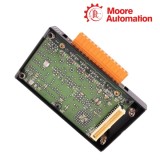
Horner HE800JCM100 / HE800JCM200 / HE800JCM205 SAE J1939 Communication Modules
Product Overview
The HE800JCM100, HE800JCM200, and HE800JCM205 are SmartStack SAE J1939 communication modules from Horner Automation. The HE800JCM100 interfaces with SAE J1587 protocol Engine Control Modules, while the HE800JCM200 and HE800JCM205 operate on the SAE J1939 CAN-based protocol used in truck and bus control networks.
The HE800JCM200 and HE800JCM205 support two communication methods: Scanning (pre-configured PGNs for continuous data gathering) and Transmit Channel (building messages in PLC registers for transmission). The HE800JCM205 adds enhanced message capabilities with 10 receive buffers and 10 transmit buffers configurable via PLC registers and ladder logic.
All three modules exchange data with the OCS/RCS host controller through the SmartStack backplane. Configuration is performed through the I/O configuration in Cscape software, using %AI, %AQ, %Q, and %I registers for module operation.
Specifications
Parameter
HE800JCM100
HE800JCM200
HE800JCM205
Brand
Horner Automation
Type
SAE J1587 Interface Module
SAE J1939 Communication Module
Country
United States
Protocol
SAE J1587
SAE J1939
SAE J1939
Baud Rate
—
250 Kbps (fixed)
250 Kbps (fixed)
Identifier
—
29-bit (CAN 2.0B)
29-bit (CAN 2.0B)
Receive Buffers
—
Scan table configured
10 receive tables
Transmit Buffers
—
Transmit Channel
10 transmit tables
Register Usage
64 %AI, 64 %AQ
11 %AQ, 2 %Q, 2 %I
14 %AQ, 16 %Q, 32 %I
Status LEDs
—
Green (OK), Orange (Traffic)
J1939 Communication Features
Scanning Method
Pre-configured PGNs for continuous data gathering
Monitor Mode — passively monitors network for PGNs
Request Mode — sends request message before data received
Scan table configuration with PGN and source address
Data stored to %AI registers for PLC access
Transmit Channel
Send data to devices on the J1939 network
Low priority request to retrieve data from devices
%AQ registers contain data to be transmitted
%Q registers control transmission timing
%I registers report transmit status
Configuration & Register Mapping
The HE800JCM100 uses 64 %AI registers and 64 %AQ registers for parameter data. The register mapping includes %AI1-45 for regular PID values, %AI46-53 for diagnostic PIDs, %AI54-60 for diagnostic SIDs, and %AI61-64 for diagnostic data.
The HE800JCM200 Transmit Channel uses 11 %AQ registers, 2 %Q registers, and 2 %I registers. The %AQ registers contain the information to be transmitted, the %Q registers control when and what to transmit, and the %I registers report the status of the transmit operation.
The HE800JCM205 uses 14 %AQ registers, 16 %Q registers, and 32 %I registers for configuration and module operation. The starting locations are configured through the I/O configuration in Cscape, and the total number of %R registers used varies depending on the configured tables.
FAQ
What is the difference between the HE800JCM100, HE800JCM200, and HE800JCM205?
The HE800JCM100 interfaces with SAE J1587 protocol Engine Control Modules and provides PID values as Analog Inputs. The HE800JCM200 operates on SAE J1939 protocol with Scanning and Transmit Channel methods. The HE800JCM205 adds enhanced message capabilities with 10 receive and 10 transmit buffers configurable via PLC registers.
What are the two communication methods supported by the HE800JCM200 and HE800JCM205?
The modules support Scanning (pre-configured PGNs for continuous data gathering) and Transmit Channel (building messages in PLC registers for transmission onto the network). Scanning uses Monitor Mode or Request Mode for each PGN.
What registers are used for module configuration and operation?
The HE800JCM100 uses 64 %AI and 64 %AQ registers. The HE800JCM200 Transmit Channel uses 11 %AQ, 2 %Q, and 2 %I registers. The HE800JCM205 uses 14 %AQ, 16 %Q, and 32 %I registers for configuration and operation.
How is the HE800JCM205 configured for J1939 network communication?
Configuration is accomplished using PLC registers and ladder logic, allowing for on-the-fly configuration changes. The module can request/monitor data from and transmit data to devices on the J1939 network using 10 receive and 10 transmit buffers.
What is the difference between Monitor Mode and Request Mode in Scanning?
In Monitor Mode, the module passively monitors the network for pre-configured PGNs and sends matching data to the PLC. In Request Mode, the module must send a request message to a device before data is sent, enabling the retrieval of data that is not regularly broadcast.
About Moore Automation
Moore Automation serves industrial maintenance teams who need to locate automation components that are no longer in active distribution. We focus on engine interface modules, communication cards, and legacy control hardware for the truck, bus, and heavy equipment industries.
Specialized sourcing for J1939 and J1587 interface modules
Support for cross-referencing discontinued part numbers
Expedited handling for production-critical orders
Consolidated shipping for multiple module requirements
Disclaimer: Moore Automation Limited is an independent reseller and is not an authorized distributor or representative of the manufacturers featured on this website. Product names and trademarks belong to their respective owners.
No related record found