GE IC694MDL645E RX3i 16-Point 24 V DC Input Module
GERX3i DISCRETE INPUT
Sixteen positive or negative logic points
GE IC694MDL645E RX3i 16-Point 24 V DC Input Module
One commoned input group for 24 V DC field signals.
Product facts
Product Overview
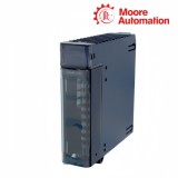
IC694MDL645E is a PACSystems RX3i discrete input module with sixteen 24 V DC points arranged in one group with a shared common. Each channel accepts positive-logic or negative-logic field wiring and transfers the filtered contact state to the controller input image.
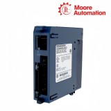
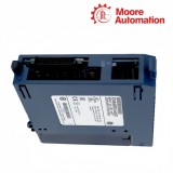
The removable nineteen-terminal block on IC694MDL645E carries inputs 1–16, the field common, an isolated 24 V DC connection and a zero-volt connection for input devices. Sixteen green indicators follow the sensed point states, while the optical input circuits separate field wiring from backplane logic.
Within an RX3i universal backplane, IC694MDL645E occupies an I/O slot and can participate in controlled hot-swap handling only after its field terminal block has been removed. The 7 ms typical response on both transitions suits ordinary machine contacts and sensor signals rather than high-speed pulse capture.
Reference values
Technical Specifications
Brand
GE
Model
IC694MDL645E
Product Name
RX3i 16-Point 24 V DC Input Module
Country
Not specified
Series
PACSystems RX3i
Input Count
16
Input Grouping
One group with common return
Rated Voltage
24 V DC
Input Range
0 to 30 V DC
Logic Type
Positive or negative logic
Typical Input Current
7 mA at 24 V DC
On-State Threshold
11.5 to 30 V DC
Off-State Range
0 to 5 V DC
Response Time
7 ms typical, on and off
Field-to-Logic Isolation
250 V AC continuous; 1500 V AC for one minute
Backplane Load
80 mA at 5 V DC with all points on
Isolated 24 V Load
125 mA with all points on
Product behavior
Product Functions
IC694MDL645E forms the boundary between sixteen field contacts and the RX3i input table.
SENSING
Translate field voltage into logic
Each optical channel compares its field voltage with defined on and off regions, then presents a stable Boolean state to the controller.
GROUP RETURN
Reference all points to one common
The shared common makes the sixteen channels one electrical group, so a common interruption affects the complete bank rather than one point.
STATUS
Expose individual point states
One LED per input gives a direct visual comparison between terminal voltage and the state delivered to the controller image.
System context
Installation Highlights
IC694MDL645E installation is organized around terminal assignment, field reference and controlled module handling.
TERMINALS
Keep channel numbering intact
Inputs 1–16 land in sequence on the removable block; preserving wire numbers makes the physical channel match the configured input reference.
FIELD POWER
Join devices to the correct reference
The 24 V DC and 0 V device connections supply the field circuit, while the common terminal establishes the logic reference for all sixteen inputs.
HANDLING
Remove the field block before hot swap
In a compatible RX3i system the module can be exchanged under controlled conditions, but the field-side terminal block must be removed first.
Practical checks
Frequently Asked Questions
Why do all sixteen IC694MDL645E inputs disappear together?
All points on IC694MDL645E share one common, so check the common conductor, field supply and terminal-block seating before tracing individual sensors.
How is positive versus negative logic checked on IC694MDL645E?
For IC694MDL645E, identify the field-device polarity and measure the active channel relative to the shared common instead of assuming the wiring convention.
What should be measured when one IC694MDL645E point stays off?
Measure the channel voltage to the IC694MDL645E common, confirm it exceeds the on-state threshold and compare the terminal, LED and controller reference.
What must be recorded before handling IC694MDL645E?
Record the IC694MDL645E slot, input references, terminal labels, common polarity, active LEDs and controller state before removing wiring or the module.
Can IC694MDL645E read a very short pulse?
IC694MDL645E has a typical 7 ms response in both directions, so a pulse shorter than the complete response and PLC scan path may not appear in logic.
Why can an IC694MDL645E LED be on while logic appears off?
For IC694MDL645E, verify that the project reads the correct slot and input reference, then compare scan timing and the current hardware configuration.
Moore Automation assigns a named sales contact to keep model identification, requested quantity, destination and available records together through an enquiry. For IC694MDL645E, terminal-block requirements, quotation details and later packing or tracking communication remain connected to the same request.
Named sales contact
One enquiry communication path
Disclaimer: Moore Automation Limited is an independent reseller and is not an authorized distributor or representative of the manufacturers featured on this website. Product names and trademarks belong to their respective owners.





No related record found