





- Positive inputs receive current from field devices and return it to the negative bus.
- Negative inputs source current toward field devices and return it to the positive bus.
- The supply wiring selects the logic direction for the complete sixteen-point group.
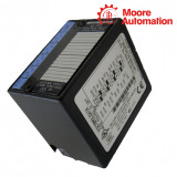
GE Fanuc IC670MDL641 48 VDC Positive/Negative Input Module
A sixteen-point 48 VDC input module configurable for positive or negative logic.
Positive/negative DC input module16 in one group48 VDC0–60 VDC
Product identity
Model Profile
GE Fanuc IC670MDL641 is a sixteen-point 48 VDC discrete input module for Field Control. All points form one group that can be wired for positive logic or negative logic, allowing the module to match the polarity convention used by the field devices.
Input networks establish the switching thresholds and provide filtering, while optoisolators separate the field group from module logic. The sixteen buffered states are transferred to the BIU as two bytes of discrete input data.
The external supply connection determines positive or negative operation; software does not reverse the field polarity. All sixteen points must use the same logic convention within the group.
Model values
Product Data
- Product type
- Positive/negative DC input module
- Input points
- 16 in one group
- Rated voltage
- 48 VDC
- Input range
- 0–60 VDC
- Input current
- 2.5 mA per point at 48 VDC
- Positive ON range
- +34 to +60 VDC
- Negative ON range
- −34 to −60 VDC
- OFF range
- 0 to ±10 VDC
- On response
- 6 ms typical; 10 ms maximum
- Off response
- 6 ms typical; 20 ms maximum
- BIU current draw
- 83 mA maximum
Hardware function
Polarity Arrangement
Selection detail
Threshold and Group Review
- Confirm that active field voltage reaches at least 34 VDC in the selected polarity.
- Verify inactive leakage remains within the 0 to ±10 VDC OFF range.
- Do not mix positive and negative logic inside the same IC670MDL641 group.
Buyer decisions
Technical Questions
Can IC670MDL641 mix sourcing and sinking sensors on one module?
No. All sixteen points share one group and must use the same positive or negative logic arrangement.
Why does a 24 VDC sensor not turn on IC670MDL641?
The module is rated for 48 VDC and the guaranteed ON range starts at 34 VDC.
How is positive or negative logic selected on IC670MDL641?
It is selected by the external supply and common wiring, not by a software polarity setting.
What should be measured when an IC670MDL641 point stays ON?
Measure inactive field voltage and leakage; the specified OFF range is 0 to ±10 VDC.
Which replacement detail matters beyond the IC670MDL641 model number?
Confirm the field polarity convention and terminal-base wiring before fitting the spare.
Does IC670MDL641 supply the 48 VDC used by the sensors?
No. The field devices require an external 48 VDC supply; the Field Control BIU supplies only the module logic power.
Product library
Product Selection
Siemens 6ES7214-1AD23-0XB0
GE IC695PBM300-BB PBM300
Omron NJ5-18GK-E2
Schneider Electric VW3M3103
Rockwell Automation 1771-AL PLC-2 I/O
Honeywell TC-MUX021
Mitsubishi Electric AJ25-AX1
Lenze EVS9321-ES/EP
SICK CLV295-0012
Beckhoff EL9512
SEW-EURODRIVE MDX61B0075-5A3-4-00 + MDX60A0074-5A3-4-00
Phoenix Contact MINI-PS-12-24DC/24DC/1
Moxa EDS-2005-EL
ABB NES002-501
Siemens 6ES7223-1BL22-0XA0
GE DS200RCIAG1AAA
Omron NJ50-FP-A2
Schneider Electric BMXDDI1602
Rockwell Automation 1771-ASB
Honeywell FC-SAI-1620M TSXPSY2600&TSXP571634&TSXDEY16D2&TSXDSY08R5&TSXAEY414&TSXRKY8
Mitsubishi Electric FX808328.5R
Lenze EVS9322-E
SICK CLV265-0012
Beckhoff EL4712
SEW-EURODRIVE MDX61B0110-5A3-4-0T/L
Phoenix Contact QUINT-PS-100-240AC/12DC/10
ABB NBUB-41C
Siemens 6ES7221-1BF22-0XA0
GE IC600 CB514K,44A717549-G01
Omron NJP3014L12 KC850
Schneider Electric TSXSCP114 RS485
Rockwell Automation 1771-OB
Honeywell CC-PAIH01 51405038-175
Mitsubishi Electric FX61002 , FX61002VDSNC
Lenze EVS9322-EP
SICK CLV432-6010
Beckhoff EL1800S
SEW-EURODRIVE MDX61B0005-5A3-4-0T
Phoenix Contact QUINT-PS/1AC/12DC/15;2866718
ABB 3BSX727503R4
Siemens 3TK2803-0BB4
GE ILI-C001 117D6684G1
Omron CPM-1300 HX/Q0/C1/S/10
Schneider Electric TSXDSY32T2K 32Q
Rockwell Automation 1771-WG
Honeywell 51454205-175 CC-PUIO01
Mitsubishi Electric FX81.CEDAGPAXANAM
Lenze EVS9322-ES
SICK CLV250-1020
Beckhoff EL9410
SEW-EURODRIVE MC07B0011-5A3-4-S0/FSC11B
ABB A157550856W
Siemens 6ES7134-4GB00-0AB0
GE IC660 ELB900C
Omron CS1W-OD232
Schneider Electric 140AVI03000 / 140AVI03000C
Rockwell Automation 1769-SM2/A
Honeywell 51400997-200
Mitsubishi Electric fx9500-81324d41-WW
Lenze EVS9323-EP


No related record found