

The 040 code defines the power boundary
DKC01.1-040-7-FW, DKC01.3-040-7-FW and DKC02.1-040-7-FW share the 40 A peak power stage. Continuous current remains 16 A at 4 kHz or 12.5 A at 8 kHz rather than 40 A.
Welcome to Moore Automation Limited


|
Copy and share this link on social network or send it to your friends
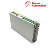
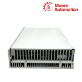
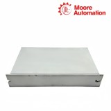
Copy| Product Name | Bosch Rexroth DKC01.1-040-7-FW / DKC01.3-040-7-FW / DKC02.1-040-7-FW ECODRIVE Drive Controllers |
| Item NO. | 2942590 |
| Weight | 0.1 kg = 0.2205 lb = 3.5274 oz |
| Category | BOSCH |
| Brand | BOSCH |
| Creation Time | 2026-11-19 |
Bosch Rexroth DKC01.1-040-7-FW, DKC01.3-040-7-FW and DKC02.1-040-7-FW are ECODRIVE drive controllers in the 40 A, 700 V-class family. Each converts a 380–480 V three-phase supply into a regulated DC bus and a controlled motor output, while the DKC01 and DKC02 identities distinguish the control-interface family and the `.1` or `.3` generation.
The common power stage of DKC01.1-040-7-FW, DKC01.3-040-7-FW and DKC02.1-040-7-FW is rated for 40 A peak, 16 A continuous at 4 kHz and 12.5 A continuous at 8 kHz. The internal bus operates from 500 to 800 V DC and connects to the inverter, braking resistor and documented X9 DC-bus extension path.
DKC01.1-040-7-FW and DKC01.3-040-7-FW belong to the DKC01 control family, whereas DKC02.1-040-7-FW uses the DKC02/SERCOS control boundary. Their 360 × 70 × 210 mm power-frame dimensions can be shared, but firmware, command communication and feedback identity must remain attached to the complete controller code.


| Attribute | DKC01.1-040-7-FW | DKC01.3-040-7-FW | DKC02.1-040-7-FW |
|---|---|---|---|
| 01Brand | Bosch Rexroth | Bosch Rexroth | Bosch Rexroth |
| 02Product type | ECODRIVE controller | ECODRIVE controller | ECODRIVE controller |
| 03Control family | DKC01 generation .1 | DKC01 generation .3 | DKC02 generation .1 / SERCOS |
| 04Power input | 3 × AC 380…480 V | 3 × AC 380…480 V | 3 × AC 380…480 V |
| 05Peak output current | 40 A | 40 A | 40 A |
| 06Continuous current at 4 kHz | 16 A | 16 A | 16 A |
| 07Continuous current at 8 kHz | 12.5 A | 12.5 A | 12.5 A |
| 08DC-bus voltage | 500…800 V | 500…800 V | 500…800 V |
| 09Control-voltage input | 19.2…28.8 V | 19.2…28.8 V | 19.2…28.8 V |
| 10Continuous power loss | 180 W | 180 W | 180 W |
| 11Braking resistor | 0.15 kW continuous / 10 kW peak | 0.15 kW continuous / 10 kW peak | 0.15 kW continuous / 10 kW peak |
| 12Dimensions | 360 × 70 × 210 mm | 360 × 70 × 210 mm | 360 × 70 × 210 mm |
| 13Mass | 4.4 kg | 4.4 kg | 4.4 kg |
| 14Protection | IP20 | IP20 | IP20 |
The electrical frame is common, but the command interface and generation remain encoded in the DKC prefix and revision.
DKC01.1-040-7-FW, DKC01.3-040-7-FW and DKC02.1-040-7-FW share the 40 A peak power stage. Continuous current remains 16 A at 4 kHz or 12.5 A at 8 kHz rather than 40 A.
DKC01.1-040-7-FW and DKC01.3-040-7-FW use the same short power code but belong to different ECODRIVE generations. Firmware and interface hardware must be checked against `.1` or `.3`, not only against 040-7.
DKC02.1-040-7-FW uses the DKC02 control family, which separates its command communication from DKC01.1-040-7-FW and DKC01.3-040-7-FW even when the power-frame ratings match.
Three connection systems meet inside the controller but serve different upstream and downstream objects.
On DKC01.1-040-7-FW, DKC01.3-040-7-FW and DKC02.1-040-7-FW, X9 provides the documented DC-bus link to approved additional bus or brake components. It is not a motor-feedback connector.
Motor feedback returns rotor information to DKC01.1-040-7-FW, DKC01.3-040-7-FW or DKC02.1-040-7-FW through the feedback interface, separate from both the high-voltage bus and command communication.
The external controller communicates through the interface defined by DKC01.1-040-7-FW, DKC01.3-040-7-FW or DKC02.1-040-7-FW. Matching only the 040-7 power code does not establish command compatibility.
When checking DKC01.1-040-7-FW / DKC01.3-040-7-FW / DKC02.1-040-7-FW, capture the type plate, firmware type plate and interface/front view for each unit so the power code and control identity are both visible.
No. They share a 040-7 power frame, but the DKC family and `.1`/`.3` generation identify different control and interface boundaries. Keep this requirement with DKC01.1-040-7-FW / DKC01.3-040-7-FW / DKC02.1-040-7-FW.
DKC01.1-040-7-FW / DKC01.3-040-7-FW / DKC02.1-040-7-FW should be recorded with this result: x9 is the documented 500–800 V DC-bus link for approved bus/brake arrangements, with the specified short cable boundary.
DKC02.1-040-7-FW carries the DKC02 control family; the two DKC01 models must not inherit its interface identity.
For DKC01.1-040-7-FW / DKC01.3-040-7-FW / DKC02.1-040-7-FW, use 16 A at 4 kHz or 12.5 A at 8 kHz; 40 A is the peak-current class.
The `FW` suffix indicates firmware is ordered separately, and the required firmware must match the controller family, generation and configured function. This condition belongs to DKC01.1-040-7-FW / DKC01.3-040-7-FW / DKC02.1-040-7-FW.

Moore Automation handles automation-component enquiries across established brands including Bosch Rexroth, Siemens, ABB, Allen-Bradley, Schneider Electric, Honeywell, GE and Emerson. The brand scope supports requests that combine controllers, drives, I/O and related industrial parts.
DKC01.1-040-7-FW, DKC01.3-040-7-FW and DKC02.1-040-7-FW are recorded as separate Bosch Rexroth identities even though they share the 040-7 power code.


Moore Automation Sales Team
Copyright © 2004–2026 www.mvme.cn. All rights reserved.
Disclaimer: Moore Automation Limited is an independent reseller and is not an authorized distributor or representative of the manufacturers featured on this website. Product names and trademarks belong to their respective owners.
No related record found