




Bently Nevada · 3300 XL 8 mm
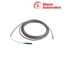
Bently Nevada 330102-04-25-10-02-00 3300 XL 8 mm Armored Proximity Probe
3/8-24 UNF standard-mount probe with a 1.0 m armored lead
Product Description
330102-04-25-10-02-00 is an armored Bently Nevada 3300 XL 8 mm standard-mount proximity probe with a 3/8-24 UNF case thread. Its order fields define a 0.4 in unthreaded length, a 2.5 in overall case and a 1.0 m standard cable with a miniature coaxial ClickLoc connector.
The probe is the sensing element in a three-part 3300 XL 8 mm proximity transducer system. Together with the matching extension cable and Proximitor Sensor, it converts the distance to a conductive target into a voltage used for static position and dynamic vibration measurements.
Approval option 00 means no agency approval is selected for 330102-04-25-10-02-00. The stainless-steel armor protects the integral lead, while the complete electrical length still has to match the selected Proximitor Sensor.
Technical Specifications
| Technical Item | 330102-04-25-10-02-00 |
|---|---|
| Brand | Bently Nevada |
| Product Type | 3300 XL 8 mm armored proximity probe |
| Brand Country | United States |
| Probe Tip Diameter | 8.0 mm (0.31 in) |
| Case Thread | 3/8-24 UNF |
| Unthreaded Length | 0.4 in |
| Overall Case Length | 2.5 in |
| Total Probe Length | 1.0 m (3.3 ft) |
| Lead Protection | Stainless-steel armor |
| Connector | Miniature coaxial ClickLoc, option 02 |
| Cable | 75 Ω FEP-insulated standard cable |
| Approval Option | 00 — not required |
| Probe Tip Material | Polyphenylene sulfide (PPS) |
| Probe Case Material | AISI 303 or 304 stainless steel |
Shaft Motion Measurement Applications
In a matched 3300 XL 8 mm system, the probe supports radial shaft vibration and axial or thrust position measurement on fluid-film bearing machines. It can also provide the changing gap signal used for phase-reference, Keyphasor and speed measurements.
The 2.5 in case and 0.4 in unthreaded section suit a threaded bracket or machine-case mounting point that accepts the 3/8-24 UNF body. The final measurement role is set by probe orientation, target geometry and the receiving monitor channel.
Armored Probe Mounting Procedure
Armored Probe Mounting Procedure in practice
Verify a clean 3/8-24 UNF mounting thread, confirm 0.4 in of unthreaded length and leave clearance for the 2.5 in case. Thread the probe into position without twisting or pulling the armored lead.
Route the 1.0 m cable with at least a 25.4 mm bend radius, connect the ClickLoc interface to the correct extension cable and protect the joint against liquid ingress. Complete the chain with the Proximitor Sensor whose calibrated length equals the probe plus extension cable, then set the working gap from the live channel.
Frequently Asked Questions
Why can a replacement 330102-04-25-10-02-00 still produce an unstable or incorrect gap value?
A mechanically correct probe can still read incorrectly if the extension cable and Proximitor Sensor do not form the required calibrated system length. Confirm the complete 3300 XL 8 mm signal chain, dry and secure the ClickLoc joint, then set the working gap from the live voltage before judging the channel.
What should be checked when the armored lead of 330102-04-25-10-02-00 will not follow the existing cable route?
Do not force the armor through a tight elbow or pull at the probe case. Re-route the 1.0 m lead with at least a 25.4 mm bend radius, support its weight and leave the ClickLoc connection accessible and protected from liquid.
How can a buyer avoid receiving 330102-04-25-10-02-00 with the wrong mechanical reach?
Verify the complete suffix against the mounting point: this configuration has 0.4 in of unthreaded length and a 2.5 in overall case with a 3/8-24 UNF thread. A probe sharing only the 330102 base number may have different reach and should not be treated as equivalent.
Can 330102-04-25-10-02-00 be installed where an approval-marked probe is required?
No approval is selected by option 00. If the measurement point is governed by a hazardous-location or other agency requirement, choose the correctly approved configuration rather than relying on mechanical similarity.
What practical checks should follow installation of 330102-04-25-10-02-00 when vibration alarms appear immediately?
Inspect the mounting for looseness, confirm that the cable is not moving against the machine and verify the probe is viewing the intended conductive target. Then check static gap voltage and channel wiring before changing alarm settings.
Company Profile
About Moore Automation
Industrial automation supply for maintenance and replacement projects
Moore Automation supplies industrial automation and electronic components for PLC, DCS, TSI, HMI, drive, sensor and control-system applications. Its inventory covers current products as well as discontinued and hard-to-find parts used to maintain legacy equipment.
Customers receive worldwide supply support, product-condition information and practical follow-up from enquiry through delivery.

No related record found