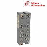
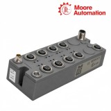
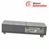
Three-wire sensor connection
At each M8 socket, pin 1 supplies +24 VDC, pin 3 supplies ground and pin 4 receives the sensor output. The module therefore powers a standard three-wire device and measures its returned switching state on one connector.
Welcome to Moore Automation Limited
Copy and share this link on social network or send it to your friends
Copy| Product Name | B&R X67DI1371 X67 IP67 Digital Input Module |
| Item NO. | 2943237 |
| Weight | 0.1 kg = 0.2205 lb = 3.5274 oz |
| Category | B&R |
| Brand | B&R |
| Creation Time | 2026-11-20 |
X67 REMOTE I/O / DIGITAL INPUT
B&R X67DI1371 is an IP67-rated X67 remote I/O module with eight 24 VDC sink digital inputs. Mounted outside the control cabinet, X67DI1371 connects sensors through eight three-pin M8 sockets and transfers their filtered states through the X2X Link M12 network connections to the controller.
Each sensor connected to X67DI1371 receives 24 V and ground from the module and returns its switching signal on the DI conductor. The input circuit applies a fixed 1 ms delay that suppresses shorter disturbance pulses, then the module collects the eight filtered channel states at a fixed offset to the network cycle and transfers them together in the same cycle.
Power and communication continue through X67DI1371 on the X2X Link and I/O-supply connectors. The I/O supply is routed between the C and D ports with reverse-polarity and sensor-supply short-circuit protection, while the channel LEDs show individual input states and the module indicators distinguish X2X power, communication and operating status.

| Brand | B&R |
|---|---|
| Product Type | X67 digital input module |
| Digital Inputs | 8 sink inputs |
| Input Voltage | 24 VDC |
| Field Connectors | 8 × M8, 3-pin |
| Network Connector | M12, B-coded X2X Link |
| Input Filter | Fixed 1 ms delay |
| Input State Transfer | Eight channels in one USINT register |
| Sensor Supply | 24 VDC from module connector |
| Sensor Supply Protection | Short-circuit protected |
| Electrical Isolation | Input channels isolated from bus |
| X2X Power Consumption | 0.75 W |
| Maximum Sensor/Actuator Consumption | 12 W total |
| I/O Power Routing | Maximum 8 A total, 4 A per connector pin |
| Status Indication | X2X status plus channel LEDs |
| Protection Rating | IP67 |
| Operating Temperature | -25 to 60°C |
The X67DI1371 input circuit links field power, a discrete sensor signal, fixed filtering and one cyclic network value.
At each M8 socket, pin 1 supplies +24 VDC, pin 3 supplies ground and pin 4 receives the sensor output. The module therefore powers a standard three-wire device and measures its returned switching state on one connector.
A 1 ms input delay rejects pulses shorter than the filter period. The delay is fixed, so application timing must account for it rather than expecting a configurable input-filter parameter.
After filtering, channels 1 through 8 are collected into one byte and transferred in the same X2X cycle. The controller can read individual bits while retaining the common sampling relationship between all eight inputs.
The sealed module carries both X2X Link and I/O power through the machine-mounted station while protecting the local sensor branches.
Pre-assembled B-coded cables connect the X2X Link input and continuation. Network status LEDs separate missing X2X power, absent communication and a module that is supplied but not yet initialized.
The C and D connectors route 24 VDC field power through the module. Current limits apply to the total path and to individual connector pins, so downstream load must be counted together with local sensor consumption.
Reverse-polarity protection guards the incoming I/O supply and short-circuit protection limits a sensor branch fault. The protection state and channel LEDs help distinguish a wiring problem from a logical input state.
For X67DI1371, include local sensor consumption and the current passed onward through the I/O supply connectors. Observe the 8 A total route, 4 A per connector pin and 12 W sensor/actuator consumption boundary.
X67DI1371 uses a fixed 1 ms input filter. A pulse shorter than the delay is intentionally suppressed; compare the sensor pulse width with the filter before troubleshooting the X2X process value.
No. The X67DI1371 input delay is fixed at 1 ms. If the application requires a different hardware filter behavior, the selection must be made at module or sensor level rather than by changing a parameter.
On the selected M8 socket of X67DI1371, use pin 1 for +24 VDC, pin 3 for ground and pin 4 for the digital input signal. Keep the sensor current within the module’s supply limits.
On X67DI1371, inspect the shared I/O supply and connector path before checking eight sensors individually. A routed-power or common-ground problem can affect multiple M8 inputs while X2X communication remains present.
X67DI1371 has separate X2X and I/O power paths. Check the B-coded X2X cables and X2X status indication instead of using the presence of sensor voltage as proof that network communication is active.
Moore Automation links packing, destination and carrier information to the confirmed model list so the dispatched package remains traceable to the enquiry.
Moore Automation Sales Team
Copyright © 2004–2026 www.mvme.cn. All rights reserved.
Disclaimer: Moore Automation Limited is an independent reseller and is not an authorized distributor or representative of the manufacturers featured on this website. Product names and trademarks belong to their respective owners.
No related record found