

01
Matched SO+ and SO− pair
The positive and negative terminals with the same channel number belong to one safe output. Wiring an actuator between those two terminals preserves the module’s ability to control both conductors.
Welcome to Moore Automation Limited



|
Copy and share this link on social network or send it to your friends
Copy| Product Name | B&R X20SO4110 X20 Safe Digital Output Module |
| Item NO. | 2943229 |
| Weight | 0.1 kg = 0.2205 lb = 3.5274 oz |
| Category | B&R |
| Brand | B&R |
| Creation Time | 2026-11-20 |
SAFEIO / TYPE A OUTPUTS
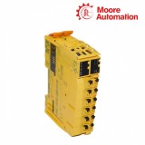
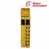
B&R X20SO4110 is a four-channel safe digital output module in the B&R X20 SafeIO family. Each output uses a type A positive-and-negative switching pair to control a floating 24 VDC actuator, while the safe application and the module electronics supervise the commanded state and place a switch-off request above standard application control.
For every channel on X20SO4110, SO+ and SO− form one actuator circuit rather than two unrelated outputs. The module reads the output level and measures current so an open circuit can be represented by CurrentOK; short test pulses are also applied to the semiconductor stage, which means the connected actuator must tolerate the specified OSSD low phase and capacitive-load boundary.
Installation of X20SO4110 uses a safety-keyed bus module and X20TB52 terminal block. The four channels share the module supply but are isolated from the X20 bus, and the terminal layout places each positive conductor opposite its matching negative conductor so that floating loads can be wired without using field ground as the return path.
| Brand | B&R |
|---|---|
| Product Type | X20 SafeIO digital output module |
| Safe Outputs | 4 |
| Output Variant | Type A FET; positive and negative switching |
| Nominal Voltage | 24 VDC |
| Nominal Current | 0.5 A per channel |
| Total Nominal Current | 2 A |
| Current Monitoring | Open-circuit detection with CurrentOK status |
| Open-Circuit Thresholds | <10 mA false; 10–50 mA undefined; >50 mA true |
| Output Readback | Yes |
| Test Pulse Length | Maximum 500 µs |
| Time Between Test Pulses | Minimum 49.5 ms |
| Maximum Capacitive Load | 100 nF |
| Electrical Isolation | Channels isolated from bus; channels not isolated from each other |
| Required Bus Module | X20BM33 or X20BM36 safety-keyed |
| Required Terminal Block | X20TB52 safety-keyed |
| Protection Rating | IP20 |
| Operating Temperature | 0 to 60°C horizontal; 0 to 50°C vertical |
Each X20SO4110 channel switches both sides of a floating load so the actuator circuit can be disconnected through the defined type A topology.
The positive and negative terminals with the same channel number belong to one safe output. Wiring an actuator between those two terminals preserves the module’s ability to control both conductors.
A channel can be exposed to standard application control after the safety function enables it. A safety-related switch-off request keeps higher priority, so standard logic cannot hold the output on against the safe state.
The module returns output level and current information to the diagnostic path. This readback supports channel supervision but does not replace the required safety application evaluation and actuator wiring design.
The diagnostic current window and semiconductor tests explain why some loads require more than a simple current rating check.
CurrentOK is false below 10 mA, undefined from 10 to 50 mA, and true above 50 mA. A lightly loaded device can therefore sit inside the undefined region even when the output voltage is present.
Periodic test pulses briefly switch the active output low. The connected contactor, valve or other floating actuator must not react incorrectly to the documented pulse length and interval.
Output wiring and actuator input capacitance affect test behavior, while inductive energy is handled by the internal switching protection within the specified limits. Load suitability must be checked as a circuit, not by nominal current alone.
The four X20SO4110 channels are rated 0.5 A each with a 2 A module total. Sum the steady currents and also check inrush, test-pulse compatibility and the derating conditions for the installed orientation.
Compare the actuator input behavior and capacitance with the X20SO4110 maximum 500 µs test pulse and 100 nF capacitive-load limit. The selected actuator circuit must tolerate the OSSD low phase.
X20SO4110 requires a safety-keyed X20BM33 or X20BM36 bus module and an X20TB52 terminal block. The safety keying and terminal assignment are part of the intended installation.
On X20SO4110, CurrentOK remains false below 10 mA. Verify that the actuator is connected between the matching SO+ and SO− terminals and that its steady current is above the monitoring threshold.
The standard application can control X20SO4110 only after the safety-related channel enable is present. A safe switch-off request always has priority, so troubleshoot the safety state before changing standard output logic.
No. Each X20SO4110 type A channel is intended for a floating actuator connected between its numbered SO+ and SO− terminals. Using field GND as the normal return bypasses the paired switching arrangement.
Moore Automation compares the received item, model label, stated condition and included scope with the confirmed order before dispatch preparation.


Moore Automation Sales Team
Copyright © 2004–2026 www.mvme.cn. All rights reserved.
Disclaimer: Moore Automation Limited is an independent reseller and is not an authorized distributor or representative of the manufacturers featured on this website. Product names and trademarks belong to their respective owners.
No related record found