

01
Pulse-coded supply
Pulse 1 and Pulse 2 can provide distinct test patterns to the sensor conductors. The returned states on SI 1 and SI 2 let the module evaluate the field signal together with expected pulse behavior.
Welcome to Moore Automation Limited


|
Copy and share this link on social network or send it to your friends
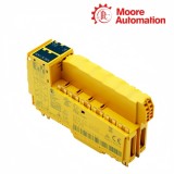
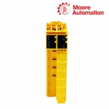
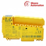
Copy| Product Name | B&R X20SC2432 X20 Safe Digital Mixed Module |
| Item NO. | 2943234 |
| Weight | 0.1 kg = 0.2205 lb = 3.5274 oz |
| Category | B&R |
| Brand | B&R |
| Creation Time | 2026-11-20 |
SAFEIO / INPUT AND RELAY OUTPUT
B&R X20SC2432 is a mixed X20 SafeIO module with two safe type A digital inputs, two diagnostic pulse outputs and two relay outputs with normally open contacts. In the B&R safety system, X20SC2432 reads a paired or independent sensor arrangement and switches two electrically isolated floating load circuits through monitored relay contacts.
Pulse 1 and Pulse 2 from X20SC2432 can feed the associated input circuits so the module can distinguish the expected sensor-line pattern from certain cross faults. The two input channels also use configurable switch-on and switch-off filters; the rising and falling delays are applied separately so contact disturbance can be suppressed without treating an external OSSD test gap as a valid off command.
The relay section of X20SC2432 exposes NO 1 / COM 1 and NO 2 / COM 2 as two isolated contact circuits. Positively driven feedback contacts are evaluated inside the module to determine contact position, while external fusing and the documented AC or DC switching limits protect the connected load path; relay contact life therefore depends on the actual load category and switching duty.
| Brand | B&R |
|---|---|
| Product Type | X20 SafeIO mixed input and relay output module |
| Safe Digital Inputs | 2 type A |
| Pulse Outputs | 2 push-pull outputs, 50 mA each |
| Input Voltage | 24 VDC -15% / +20% |
| Hardware Input Filter | ≤150 µs |
| Software Input Filter | 0 to 500 ms |
| Input Error Detection Time | 100 ms |
| Relay Outputs | 2 normally open contacts |
| Relay Contact Arrangement | NO 1 / COM 1 and NO 2 / COM 2 |
| Switching Range | 5 to 24 VDC; 5 to 48 VAC |
| Maximum Switching Capacity | 48 VAC / 6 A or 24 VDC / 6 A within load-category limits |
| Relay Switching Delay | <50 ms on and <50 ms off |
| Diagnostic Principle | Contact position from positively driven feedback contacts |
| Electrical Isolation | Channel-to-bus and channel-to-channel isolation |
| External Protection | 6 A gL/gG fuse or C-characteristic 1.6 A breaker |
| Required Accessories | Safety-keyed bus module and terminal block |
| Operating Temperature | 0 to 60°C horizontal; 0 to 50°C vertical |
The input and pulse terminals of X20SC2432 form a diagnostic measurement chain rather than independent general-purpose I/O points.
Pulse 1 and Pulse 2 can provide distinct test patterns to the sensor conductors. The returned states on SI 1 and SI 2 let the module evaluate the field signal together with expected pulse behavior.
Switch-on filtering delays a rising edge to suppress short disturbances, while switch-off filtering can suppress brief low gaps from electronic OSSD sensors. Each delay must match the actual sensor behavior and safety response calculation.
When the two inputs represent one dual-channel device, the configured discrepancy time determines how long their states may differ. The signal pair becomes valid only within the selected simultaneity relationship.
The X20SC2432 output path combines a commanded relay coil, positively driven feedback and an externally protected load circuit.
Each NO/COM pair switches its own external AC or DC supply. The two contact channels are isolated, so the load source does not originate from the module’s 24 V electronics supply.
Positively driven contacts allow the module to compare the commanded relay state with the mechanical contact position. A disagreement becomes diagnostic information rather than being inferred only from the external load.
Contact current, voltage, load category and switching rate determine relay wear. The external fuse or breaker protects the fault-current path, while the application must keep normal switching within the documented contact capacity.
If an electronic OSSD sensor supplies its own line monitoring, configure the X20SC2432 input arrangement for that sensor instead of feeding it an incompatible pulse pattern. Preserve the documented wiring and filter behavior for the selected mode.
For X20SC2432, compare the commanded state with the internal positively driven contact feedback, then inspect the load protection and switching duty. Do not treat the diagnostic as only an external load-current issue.
Yes. X20SC2432 provides channel-to-channel isolation for its relay contacts. Each NO/COM pair can belong to its own permitted external circuit, provided the voltage, current and installation limits are observed.
The configured switch-on or switch-off delay on X20SC2432 is added to the module and network response path. Use the chosen values in the safety response calculation rather than setting long filters only to hide unstable wiring.
On X20SC2432, compare SI 1 and SI 2 timing with the configured discrepancy limit and input filters. Both channels can change visibly yet still fail the required simultaneity relationship.
The NO/COM contacts on X20SC2432 switch an external load circuit. Use the specified 6 A gL/gG fuse or C-characteristic 1.6 A breaker so a short circuit remains within the relay contact protection boundary.
Moore Automation keeps original order numbers and safety-related accessory references visible when reviewing legacy or specialized automation components.


Moore Automation Sales Team
Copyright © 2004–2026 www.mvme.cn. All rights reserved.
Disclaimer: Moore Automation Limited is an independent reseller and is not an authorized distributor or representative of the manufacturers featured on this website. Product names and trademarks belong to their respective owners.
No related record found