

01
Interface separation
IF1 and IF2 do not share a CAN transceiver or network reference. Each channel has its own SJA1000 controller, connector and termination switch, allowing two bus segments to run with different node arrangements.
Welcome to Moore Automation Limited

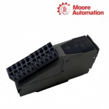
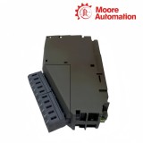
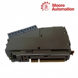

|
Copy and share this link on social network or send it to your friends
Copy| Product Name | B&R X20IF2772 X20 Dual CAN Interface Module |
| Item NO. | 2943216 |
| Weight | 0.1 kg = 0.2205 lb = 3.5274 oz |
| Category | B&R |
| Brand | B&R |
| Creation Time | 2026-11-20 |
CAN COMMUNICATION / DUAL INTERFACE
B&R X20IF2772 is a dual-CAN communication interface module for the B&R X20 control system. Installed in an X20 controller expansion slot, X20IF2772 gives the controller two independent CAN paths so application-specific devices or separate CAN segments can exchange telegrams with the PLC without sharing one physical interface.
Both CAN channels on X20IF2772 use their own five-pin multipoint connector, SJA1000 controller and switchable terminating resistor. IF1 and IF2 are electrically isolated from the PLC and from each other, so the two networks retain separate electrical reference paths; the node-number switches and the CAN transmit and termination LEDs apply independently to each channel.
Connection work on X20IF2772 therefore follows two parallel signal chains: CAN high, CAN low, CAN ground and shield enter the selected interface, the assigned controller processes the telegram, and the PLC receives the resulting communication data. Each interface requires its own separately ordered TB2105 terminal block, and an integrated resistor should be enabled only when that interface is located at the end of its CAN segment.
| Brand | B&R |
|---|---|
| Product Type | X20 dual CAN interface module |
| System Role | Application-specific controller expansion |
| CAN Interfaces | 2 |
| Connector per Interface | 5-pin male multipoint connector |
| Controller per Interface | SJA1000 |
| Maximum Transfer Rate | 1 Mbit/s |
| Maximum Distance | 1000 m |
| Terminating Resistors | Two integrated, individually switchable |
| Electrical Isolation | PLC isolated from IF1 and IF2; IF1 isolated from IF2 |
| Node Number Setting | Two hexadecimal switches |
| Status Indication | Module, transmit and termination LEDs |
| Power Consumption | 1.2 W |
| Required Terminal Blocks | 2 × TB2105, ordered separately |
| Protection Rating | IP20 |
| Operating Temperature | -25 to 60°C horizontal; -25 to 50°C vertical |
The internal organization of X20IF2772 keeps each fieldbus connection separately addressable from connector to controller.
IF1 and IF2 do not share a CAN transceiver or network reference. Each channel has its own SJA1000 controller, connector and termination switch, allowing two bus segments to run with different node arrangements.
A frame arriving on one connector passes through that interface controller before it is exposed to the X20 controller application. Traffic on the second connector follows a separate path and does not become an electrical extension of the first bus.
The status area distinguishes transmit activity and enabled termination for CAN 1 and CAN 2. Commissioning checks can therefore start with the affected interface instead of treating the module as one undivided communication port.
Correct CAN operation depends on the relationship between node settings, connector wiring and the physical end of each segment.
The hexadecimal switches set the CAN node number used by the configured interface function. The physical setting and the controller project must describe the same node assignment before message exchange is expected.
Each built-in resistor is controlled by its own switch on the module. It is enabled when the corresponding interface is at a segment end and left disabled when the bus continues through that station.
TB2105 exposes CAN ground, CAN low, shield, CAN high and the remaining terminal position for each interface. Keeping the pair and shield relationship intact prevents the two independent channels from being cross-wired.
On X20IF2772, confirm that the project uses IF1, the CAN 1 node number matches the switch setting, and CAN high, CAN low and CAN ground are landed on the first TB2105 connector. The TxD CAN 1 LED should respond only when that channel transmits.
Enable the CAN 2 resistor on X20IF2772 only when IF2 is at the physical end of that CAN segment. If another station or cable continues beyond the module, leave the resistor off and terminate the actual segment end.
No. X20IF2772 keeps IF1 and IF2 electrically isolated from the PLC and from each other. Any data relationship between the networks must be implemented in the controller application rather than by bridging their conductors.
For the inactive X20IF2772 channel, compare its connector wiring, node switch, transfer-rate configuration and end termination with the working segment. The two interfaces have separate hardware, so the working channel does not validate the other wiring.
X20IF2772 requires two separately ordered TB2105 terminal blocks, one for IF1 and one for IF2. Select the screw-clamp or push-in version while preserving the same five-position CAN assignment.
X20IF2772 does not support CAN RTR messages that use extended 29-bit identifiers. If the connected protocol depends on that request format, verify the message design before assigning the interface.
Moore Automation keeps the complete manufacturer and model string attached to every enquiry, document check and commercial update.


Moore Automation Sales Team
Copyright © 2004–2026 www.mvme.cn. All rights reserved.
Disclaimer: Moore Automation Limited is an independent reseller and is not an authorized distributor or representative of the manufacturers featured on this website. Product names and trademarks belong to their respective owners.
No related record found