

Short circuit and overload
Excess current raises the output-stage temperature and causes the affected channel to switch off. If the field fault remains, repeated recovery attempts can make the output appear to pulse rather than stay permanently off.
Welcome to Moore Automation Limited



|
Copy and share this link on social network or send it to your friends
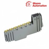
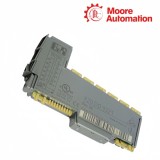
Copy| Product Name | B&R X20DO9321 X20 Digital Output Module |
| Item NO. | 2940469 |
| Weight | 0.1 kg = 0.2205 lb = 3.5274 oz |
| Category | B&R |
| Brand | B&R |
| Creation Time | 2026-11-18 |
B&R X20DO9321 is a 12-channel negative-switching digital output module for the B&R X20 control system. X20DO9321 receives output data from the controller and uses its 24 VDC FET stages to complete the return path for connected one-wire loads.
With X20DO9321, each active channel switches up to its permitted individual load while the combined current of all twelve outputs remains within the module total. The negative-switching stage connects the load toward the return side, so the external supply, load and common conductor must form the current path shown for a sink output.
X20DO9321 monitors the output stage after the controller issues a command. Thermal cutoff responds to an overload or short circuit, the internal inverse diode carries current from an inductive load when the channel turns off, and channel indication plus software diagnostics distinguish the requested output state from a monitored electrical fault.
| Specification | X20DO9321 |
|---|---|
| Product type | 12-channel digital output module |
| Output stage | FET, negative-switching sink |
| Operating voltage | 24 VDC −15% / +20% |
| Nominal channel current | 0.5 A |
| Total nominal current | 6 A |
| Connection type | 1-wire |
| Protection | Thermal cutoff for overcurrent or short circuit |
| Peak short-circuit current | <7 A |
| Output monitoring | 10 ms diagnostic delay |
| Leakage current off | 75 µA |
| RDS(on) | 120 mΩ |
| Switching delay | <300 µs on and off |
| Resistive switching frequency | Maximum 500 Hz |
| Inductive-load clamp | Internal inverse diode; typical 50 VDC braking voltage |
| Bus / internal I/O power | 0.26 W / 0.99 W |
| Temperature | −25 to 60°C horizontal; −25 to 50°C vertical |
| Required accessories | X20BM11 and X20TB12 ordered separately |
| Degree of protection | IP20 |
X20DO9321 combines a negative-switching FET stage with thermal cutoff and an inductive-current path, so protection behavior can be traced from the connected load back to one output channel.
Excess current raises the output-stage temperature and causes the affected channel to switch off. If the field fault remains, repeated recovery attempts can make the output appear to pulse rather than stay permanently off.
When a coil is switched off, stored energy continues through the module’s internal inverse-diode path. The connected load and switching duty must remain within the output conditions because the diode controls the current path rather than removing the load energy.
The FET output is not an ideal mechanical contact and a small leakage path remains when it is off. Sensitive electronic loads can therefore show residual voltage even though the command and channel indication are inactive.
X20DO9321 exposes the commanded channel state and output fault information separately, allowing the control command, output electronics and field wiring to be checked in sequence.
An active process command confirms what the controller requested, not that current reached the actuator. Compare the command, orange channel indication and voltage across the load to locate where the output path stops.
A red module indication and software output error identify a monitored fault condition. Disconnecting the affected load separates a shorted conductor or actuator from an output-stage fault without disturbing unrelated channels.
After the field fault is removed, observe whether the output returns without a recurring error. A fault that clears only with the load disconnected points back to wiring or actuator current rather than to the control command.
X20DO9321 is a negative-switching sink module, so a load wired for positive switching has the wrong current path; compare the field circuit with the X20DO9321 connection diagram.
For X20DO9321, isolate the affected load, measure current and wiring resistance, inspect for a short to supply, and then confirm whether the channel recovers without the field device connected.
X20DO9321 is rated at 0.5 A per channel and 6 A total, but cabinet temperature, simultaneous loading and module power dissipation still determine the acceptable continuous pattern.
X20DO9321 has a specified off-state leakage current, so very sensitive electronic loads may show residual voltage; verify the load threshold or add an approved bleed solution.
X20DO9321 includes an inverse diode and defined braking behavior, but coil energy, duty cycle and maximum switching frequency must still be checked for the actual actuator.
X20DO9321 can cycle its protected output while an overload or short circuit remains; disconnect the affected load and inspect its conductor path if the channel repeatedly recovers and faults again.
Moore Automation combines product sourcing, documentation handling and order coordination for industrial automation components. Each service step uses the confirmed brand and model as its reference.
The confirmed model is checked through the relevant supply channels.
Available manuals, data sheets and item information can be kept with the enquiry.
Packing, destination and carrier details are organized after confirmation.


Moore Automation Sales Team
Copyright © 2004–2026 www.mvme.cn. All rights reserved.
Disclaimer: Moore Automation Limited is an independent reseller and is not an authorized distributor or representative of the manufacturers featured on this website. Product names and trademarks belong to their respective owners.
No related record found