

Welcome to Moore Automation Limited

0
Loadding...
 

sales@mvme.cn    Phone: +86 18030175807

Home>B&R>B&R X20DO6321 / X20DO8331 X20 Digital Output Modules
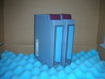
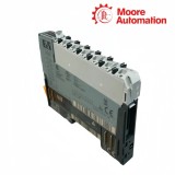
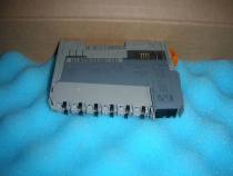
B&R X20DO6321 / X20DO8331 X20 Digital Output Modules

B&R X20DO6321 / X20DO8331 X20 Digital Output Modules Item NO.: 2942562

Write a Review
US$ 1.00
Quantity
Stock ( 28 )

Copy and share this link on social network or send it to your friends

Copy
Request Price & AvailabilitySend the part number and quantity. Our team will confirm stock, condition, lead time and the best quotation.
  • MOQ: 1 piece
  • International shipping
  • 1-year warranty on eligible items
  • Fast response during business hours
Product Name B&R X20DO6321 / X20DO8331 X20 Digital Output Modules
Item NO. 2942562
Weight 0.1 kg = 0.2205 lb = 3.5274 oz
Category B&R
Brand B&R
Creation Time 2026-11-19

B&R X20DO6321 / X20DO8331 X20 Digital Output Modules
DOX20 Module

DIGITAL I/O / SINK OUTPUTS

B&R X20DO6321 / X20DO8331 X20 Digital Output Modules

6 / 8sink channels
01

Product Overview

B&R X20DO6321 and X20DO8331 are 24 VDC sink-output modules for the B&R X20 I/O system. X20DO6321 provides six 0.5 A channels and distributes actuator power through the station terminal arrangement, while X20DO8331 provides eight 2 A channels and accepts a separately fused external 24 VDC supply directly on the module.

The six outputs of X20DO6321 share the internal actuator supply path and can be wired in one- or two-wire arrangements according to the selected terminal block. The eight outputs of X20DO8331 are organized across two output drivers, channels 1–4 and 5–8, so current distribution and the documented derating limits must be checked by driver group rather than only as one module total.

Both X20DO6321 and X20DO8331 compare commanded and actual output state, indicate channel activity, and use thermal shutdown for overload or short circuit. X20DO8331 also permits defined parallel-channel arrangements and delayed switching control, which require matching software configuration and field wiring before higher current is assigned to a load.

02

Product Data

Specification X20DO6321 X20DO8331
Brand B&R B&R
Product Name X20 Digital Output Module X20 High-Current Digital Output Module
Country Austria Austria
Output Quantity 6 8
Output Circuit 24 VDC sink 24 VDC sink
Nominal Current per Channel 0.5 A 2 A
Actuator Supply Through station I/O supply path External 24 VDC supply connected on module
Connection Style 1-wire or 2-wire 1-wire outputs plus supply and GND
Driver Organization Six channels on common module stage Channels 1–4 and 5–8 on separate output drivers
Output Monitoring Target/actual comparison, 10 ms delay Target/actual comparison, 10 ms delay
Protection Thermal shutdown for overcurrent or short circuit Thermal shutdown, reverse-polarity protection on external supply
Parallel Operation Not specified as a current-increase function Supported in documented channel combinations
Delayed Output Function Standard cyclic output transfer Per-channel delay mask with 100 µs timer base
Operating Temperature -25 to 60°C horizontal; -25 to 50°C vertical -25 to 60°C horizontal; -25 to 50°C vertical with derating
Required Station Parts X20BM11; X20TB06 or X20TB12 X20BM11 and X20TB12
Degree of Protection IP20 IP20
03

Current Distribution Strategy

Load planning is governed by the way each module receives and distributes actuator current.

01

Station-fed six-channel path

X20DO6321 takes actuator energy from the X20 station supply and routes it to six low-side output stages. The calculation must include the supply module, terminal path and all simultaneously energized channels, not only the rating of one output.
02

Externally fed driver groups

X20DO8331 brings a fused external supply into the module and divides the eight channels across two driver groups. The group arrangement matters when several high-current loads switch together because heating and the permitted current envelope are evaluated across those drivers.

03

Parallel-channel planning

Parallel outputs on X20DO8331 are a configured electrical arrangement, not an automatic result of joining conductors. The selected channels must switch together and follow the documented grouping so unequal timing or wiring resistance does not push current into one stage.

04

Output Timing and Recovery

Command timing, monitored state and thermal recovery explain why a load can respond differently from the raw controller bit.

01

Cyclic command path

X20DO6321 transfers six output bits through the normal cyclic image. A mismatch between process data and the actuator is checked through supply, terminal and monitoring status before controller logic is changed.

02

Delayed channel path

X20DO8331 can select channels through an output-delay mask and apply delayed data with a 100 µs timer base. The application must document which channels use the direct register and which use the delayed value to avoid an unexpected staggered start.

03

Thermal retry behavior

After an overload, both modules can attempt recovery after the output stage cools. A repeating on/off symptom therefore indicates that the load fault or current condition remains; the field circuit must be corrected before stable operation returns.

05

Questions About This Product

What shared fault can stop several X20DO6321 or X20DO8331 loads at the same time?

A shared station supply issue can affect X20DO6321, while a fuse, external feed or driver-group condition can affect several X20DO8331 channels; test the shared power boundary before replacing individual loads.

When overload indications appear on X20DO6321 and X20DO8331, what must be cleared before reset?

For X20DO6321 and X20DO8331, remove the field fault, measure current, inspect the load return and allow the thermal stage to recover; on X20DO8331 also check the affected driver group and external supply.

Which power boundary makes X20DO8331 require a separate supply check when X20DO6321 is healthy?

X20DO6321 receives actuator power through the station path, while X20DO8331 uses an external 24 VDC feed on the module; verify the X20DO8331 fuse, polarity and GND even if X20DO6321 operates normally.

How should X20DO8331 parallel outputs be commissioned compared with X20DO6321?

Document the permitted X20DO8331 channel combination, common command timing and equal conductor paths before parallel operation; X20DO6321 does not use that current-increase arrangement.

Why can X20DO8331 outputs switch at different times while X20DO6321 outputs do not?

X20DO8331 supports a per-channel output-delay mask and delayed register, whereas X20DO6321 uses its normal cyclic output mapping; inspect the X20DO8331 delay configuration before treating the timing as a hardware fault.

Can the 2 A rating of X20DO8331 be applied to X20DO6321 channels?

No. X20DO6321 is rated for 0.5 A per channel, while X20DO8331 has 2 A channels with different supply and thermal rules; do not transfer the X20DO8331 load plan to X20DO6321.

06

Warehouse Availability Review

Moore Automation

https://www.mvme.cn

Moore Automation reviews requested model identity and available condition before commercial details are issued.

Line-item controlEach enquiry line keeps its own model, quantity and condition requirement.
Accessory checkRequested terminal blocks, cables or companion modules are recorded separately.
Packaging reviewPackaging condition and included items are confirmed against the same part record.
Delivery alignmentDestination and requested timing are reviewed before dispatch preparation.

No related record found

You May Also Like

Copyright © 2004–2026 www.mvme.cn. All rights reserved.

Disclaimer: Moore Automation Limited is an independent reseller and is not an authorized distributor or representative of the manufacturers featured on this website. Product names and trademarks belong to their respective owners.