



Welcome to Moore Automation Limited

0
Loadding...
 

sales@mvme.cn    Phone: +86 18030175807

Home>B&R>B&R X20DI9372 X20 Digital Input Module
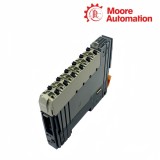
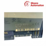
B&R X20DI9372 X20 Digital Input Module

B&R X20DI9372 X20 Digital Input Module Item NO.: 2940468

Write a Review
US$ 1.00
Quantity
Stock ( 28 )

Copy and share this link on social network or send it to your friends

Copy
Request Price & AvailabilitySend the part number and quantity. Our team will confirm stock, condition, lead time and the best quotation.
  • MOQ: 1 piece
  • International shipping
  • 1-year warranty on eligible items
  • Fast response during business hours
Product Name B&R X20DI9372 X20 Digital Input Module
Item NO. 2940468
Weight 0.1 kg = 0.2205 lb = 3.5274 oz
Category B&R
Brand B&R
Creation Time 2026-11-18

B&R X20DI9372 X20 Digital Input Module
B&R X20 System

B&R X20DI9372X20 Digital Input Module

12 source inputs24 VDC Type 11-wire connectionsConfigurable filter
Configuration snapshot
Input circuitSource
Connection type1-wire
Input characteristicEN 61131-2 Type 1
01

Product Summary

B&R X20DI9372 is a 12-channel source-input module for the B&R X20 control system. X20DI9372 receives 24 VDC Type 1 field signals through one-wire input connections and transfers the evaluated state of each channel to the controller over the X20 bus.

Each X20DI9372 channel uses one signal terminal, while the established station common completes the field-current path for the connected sensors. Because the channels share that reference, an interruption in the common path can affect several input states even when their individual signal conductors remain connected.

Inside X20DI9372, the hardware filter acts on the electrical input before the configured software delay produces the process value. The per-channel LED follows the evaluated input, while the module run/error indication reports the condition of the module, allowing the field signal, filtered channel state and module status to be read separately.

02

Specification Details

Specification X20DI9372
Product type 12-channel digital input module
Input circuit Source
Connection type 1-wire
Input characteristic EN 61131-2 Type 1
Input voltage 24 VDC −15% / +20%
Typical input current 3.75 mA at 24 VDC
Hardware filter ≤100 µs
Software filter Default 1 ms; 0–25 ms in 0.2 ms steps
Input resistance Typical 6.4 kΩ
Switching thresholds Low <5 VDC; high >15 VDC
Bus power 0.18 W
Internal I/O power 1.75 W
Diagnostics Run/error and per-channel status via LED/software
Isolation 500 Veff channel group to bus
Temperature −25 to 60°C horizontal; −25 to 50°C vertical
Humidity 5–95% RH non-condensing
Protection IP20
Required accessories X20BM11 and X20TB12 ordered separately
Pitch 12.5 +0.2 mm
03

Product Features

X20DI9372 concentrates twelve source-input points in a one-wire terminal arrangement, with the station common completing the field-current path for every connected channel.

01

Shared common reference

Each field signal reaches one input terminal while its return is provided through the established station common. A loose or incorrectly referenced common can therefore affect several otherwise unrelated sensors at the same time.

02

Channel organization

The front indication follows individual input points even though the wiring shares a common reference. Keeping terminal numbers and cable labels aligned lets a measured field voltage be compared with the matching online channel rather than a neighboring point.

03

Source-input compatibility

The field device must create the current path expected by a source-input circuit. A sensor output intended for the opposite polarity can measure supply voltage at the terminal yet still fail to produce the required input current.

04

Diagnostics

X20DI9372 applies physical input filtering before the configurable software delay, then presents the evaluated channel state through LEDs and process data.

01

Signal path through both filters

A short disturbance is handled by the input electronics before the configured delay is applied. The channel value changes only after the signal remains in the new state for the selected delay, so measured voltage and online state may not change simultaneously.

02

Single-channel comparison

When one point disagrees with the field device, compare terminal voltage, the channel LED and the online process value for that same input. Agreement on neighboring channels does not validate the conductor or sensor connected to the affected terminal.

03

Module condition versus input state

Run/error indication describes the operating condition of the module, while green channel LEDs describe evaluated inputs. This separation shows whether diagnosis should begin at the station and module or at a specific field circuit.

05

Questions & Answers

01FAQ

Why does X20DI9372 show no input state after a sensor replacement?

X20DI9372 uses source inputs and 1-wire connections; verify the replacement sensor polarity, station common, 24 VDC level and correct terminal before changing the software filter.

02FAQ

How should contact bounce be handled on X20DI9372?

Increase the X20DI9372 software input delay only enough to suppress the measured bounce, keeping the required machine response time and safety logic outside this standard input module in mind.

03FAQ

What voltage indicates a valid high on X20DI9372?

X20DI9372 specifies a high switching threshold above 15 VDC and a low below 5 VDC; a value between them calls for field-voltage and wiring investigation.

04FAQ

Why can several X20DI9372 inputs fail after work on one common conductor?

X20DI9372 uses a one-wire input arrangement referenced to the station common, so inspect common continuity and terminal distribution when several channels change together before replacing individual sensors.

05FAQ

How is a single faulty channel distinguished on X20DI9372?

For X20DI9372, compare the channel LED, online input value and measured terminal voltage; if only one point disagrees, inspect that sensor and terminal before replacing the whole module.

06FAQ

Why does an X20DI9372 channel LED change later than the measured sensor voltage?

X20DI9372 evaluates the physical input through its hardware stage and configured software delay, so compare the selected delay with the signal duration before treating the later LED transition as a channel fault.

06

Obsolete Parts Support

Moore Automation

https://www.mvme.cn/

Moore Automation accepts enquiries for discontinued and hard-to-find automation hardware. Legacy requests remain tied to the original manufacturer string, revision and associated station parts so nearby models are not silently substituted.

Legacy model records
Suffix verification
Associated-part checking
No silent substitution
LEGACY CHECK 01

Installed identity

The original nameplate, revision and system position are recorded.

LEGACY CHECK 02

Sourcing record

Available supply responses are compared with the exact legacy request.

LEGACY CHECK 03

Difference disclosure

Any model or condition difference is stated for review instead of being treated as equivalent.

Contact DetailsMoore Automation

CompanyMoore Automation
ManagerLeonia

No related record found

You May Also Like

Copyright © 2004–2026 www.mvme.cn. All rights reserved.

Disclaimer: Moore Automation Limited is an independent reseller and is not an authorized distributor or representative of the manufacturers featured on this website. Product names and trademarks belong to their respective owners.