

State and count are separate
A channel can report a steady digital state while its counter records positive transitions. Reading both values helps distinguish a stopped pulse stream from a signal that remains continuously high.
Welcome to Moore Automation Limited



|
Copy and share this link on social network or send it to your friends
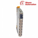
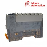
Copy| Product Name | B&R X20DI2377 X20 Digital Input and Counter Module |
| Item NO. | 2940471 |
| Weight | 0.1 kg = 0.2205 lb = 3.5274 oz |
| Category | B&R |
| Brand | B&R |
| Creation Time | 2026-11-18 |
B&R X20DI2377 is a two-channel digital input and event-counter module for the B&R X20 control system. X20DI2377 receives 24 VDC signals from three-wire sensors, transfers their digital states to the controller and counts positive input edges for pulse-based process data.
On X20DI2377, each input has its own cyclic 16-bit event counter, while one selected channel can also supply the gate-time measurement. The digital state, edge count and gate result are separate process values, so a steady high signal can coexist with a count that changes only when another positive edge arrives.
X20DI2377 uses the sensor supply, return and signal conductors as one complete field circuit. X20TB06 provides the intended terminal arrangement, X20TB12 is also permitted, and the selected X20BM11 or X20BM15 bus module connects the input electronics to power and X20 bus communication without changing the two channel functions.
| Specification | X20DI2377 |
|---|---|
| Product type | Digital input / counter module |
| Input quantity | 2 |
| Nominal voltage | 24 VDC |
| Input circuit | Sink |
| Connection type | 3-wire |
| Input characteristic | EN 61131-2 Type 1 |
| Typical input current | 10.5 mA at 24 VDC |
| Hardware filter | ≤10 µs |
| Software filter | Default 0 ms; 0–25 ms in 0.2 ms steps |
| Input resistance | Typical 2.23 kΩ |
| Switching thresholds | Low <5 VDC; high >15 VDC |
| Event counters | 2, positive-edge evaluation |
| Counter frequency | Maximum 50 kHz |
| Counter size | 16-bit |
| Gate measurement | 1 channel |
| Bus / internal I/O power | 0.15 W / 0.82 W |
| Isolation | 500 Veff channel group to bus |
| Terminal block | X20TB06 intended; X20TB12 permitted |
| Bus modules | X20BM11 or X20BM15 |
| Protection | IP20 |
X20DI2377 presents two ordinary input states, two cyclic edge counts and one selectable gate-time measurement, so the application assigns a distinct role to each returned value.
A channel can report a steady digital state while its counter records positive transitions. Reading both values helps distinguish a stopped pulse stream from a signal that remains continuously high.
Only one input is used for gate-time measurement at a time. The project must select that channel explicitly and keep its measurement result separate from the two independent event-counter values.
The native counter repeats after its maximum value. When the machine needs a cumulative total, the application reads the cyclic value often enough to detect wraparound and maintain the extended count without changing the module’s raw data.
X20DI2377 uses a three-wire sensor connection and permits alternative terminal and bus-module choices, but those hardware options do not change its two input channels or counter functions.
X20TB06 provides the intended compact terminal arrangement, while X20TB12 can be used where the station standardizes on the larger block. The extra physical positions on X20TB12 remain unused by this module.
X20BM11 supplies the normal bus position; X20BM15 adds a node-number switch for station architecture. Selecting X20BM15 changes node identification hardware, not the input frequency or counter data format.
Each sensor uses supply, return and signal conductors. Counter reliability therefore depends on the complete three-wire path, and a voltage check at the signal terminal alone does not confirm the sensor supply and return under load.
On X20DI2377, confirm the software filter is not lengthening the pulse, verify pulse width and amplitude, and measure the signal at the terminal before changing the counter task.
X20DI2377 counters are cyclic 16-bit values, so the application must sample often enough and extend rollover in software when a cumulative count beyond 65,535 is required.
X20DI2377 provides two event counters but only one gate-time measurement function, so the project must select which channel uses the gate measurement.
X20DI2377 may show a static state while missing fast edges if the software filter, sensor output, cable capacitance or task handling is unsuitable for the pulse frequency.
X20DI2377 is designed for X20TB06, while X20TB12 is permitted for standardization; choose one, document the terminal numbering and do not infer additional I/O from the larger block.
Use X20BM15 with X20DI2377 when the station requires the bus module’s node-number switch; choose X20BM11 for the normal keyed base, since the counter functions remain the same on either base.
Moore Automation coordinates protective packing, carrier selection and shipment tracking for automation hardware. Destination and handling details are reviewed with the confirmed order before dispatch.
The component is prepared for shipment with handling and protection appropriate to the item.
Available courier or forwarding arrangements are matched to the destination.
Dispatch and tracking details are returned against the confirmed order.


Moore Automation Sales Team
Copyright © 2004–2026 www.mvme.cn. All rights reserved.
Disclaimer: Moore Automation Limited is an independent reseller and is not an authorized distributor or representative of the manufacturers featured on this website. Product names and trademarks belong to their respective owners.
No related record found