


Welcome to Moore Automation Limited

0
Loadding...
 

sales@mvme.cn    Phone: +86 18030175807

Home>B&R>B&R X20CP3586 / X20CP3585 X20 Controller Modules
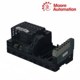
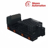
B&R X20CP3586 / X20CP3585 X20 Controller Modules

B&R X20CP3586 / X20CP3585 X20 Controller Modules Item NO.: 2940463

Write a Review
US$ 1.00
Quantity
Stock ( 28 )

Copy and share this link on social network or send it to your friends

Copy
Request Price & AvailabilitySend the part number and quantity. Our team will confirm stock, condition, lead time and the best quotation.
  • MOQ: 1 piece
  • International shipping
  • 1-year warranty on eligible items
  • Fast response during business hours
Product Name B&R X20CP3586 / X20CP3585 X20 Controller Modules
Item NO. 2940463
Weight 0.1 kg = 0.2205 lb = 3.5274 oz
Category B&R
Brand B&R
Creation Time 2026-11-18

B&R X20CP3586 / X20CP3585 X20 Controller Modules
B&R X20 System

B&R X20CP3586 / X20CP3585X20 Controller Modules

Three interface slotsGigabit Ethernet1 MB SRAMFanless controller
Configuration snapshot
Processor tierAtom 1.6 GHz compatible / Atom 1.0 GHz compatible
Working memory512 MB DDR2 SDRAM / 256 MB DDR2 SDRAM
User RAM1 MB SRAM
01

Model Overview

B&R X20CP3586 and X20CP3585 are three-slot X20 controller modules for the B&R X20 control system. X20CP3586 and X20CP3585 execute the machine application, coordinate the local X20 I/O station and connect that control task to Ethernet, POWERLINK and optional interface modules.

The processing tier separates X20CP3586 from X20CP3585 without changing their external port arrangement. X20CP3586 combines a 1.6 GHz Atom processor with 512 MB DDR2 working memory, while X20CP3585 uses a 1.0 GHz Atom processor with 256 MB DDR2; in both controllers, CompactFlash stores the application and SRAM holds retained user data.

Three interface slots on X20CP3586 and X20CP3585 extend the controller with project-selected communication hardware. Their built-in Gigabit Ethernet port handles standard network exchange, POWERLINK serves the configured real-time network, X2X Link connects the local module chain, and the common CPU/X2X supply powers the controller and its downstream X2X path.

02

Technical Details

Specification X20CP3586 X20CP3585
Product type X20 controller module X20 controller module
Processor tier Atom 1.6 GHz compatible Atom 1.0 GHz compatible
Working memory 512 MB DDR2 SDRAM 256 MB DDR2 SDRAM
User RAM 1 MB SRAM 1 MB SRAM
Application memory CompactFlash; ordered separately CompactFlash; ordered separately
Interface slots 3 3
Ethernet 10/100/1000 Mbit/s 10/100/1000 Mbit/s
POWERLINK V1/V2, 100 Mbit/s V1/V2, 100 Mbit/s
X2X Link Master Master
RS232 X20TB12; max. 115.2 kbit/s X20TB12; max. 115.2 kbit/s
USB 2 × USB 1.1/2.0 Type A 2 × USB 1.1/2.0 Type A
Cooling Fanless Fanless
Diagnostics CPU, CF, battery, Ethernet, POWERLINK, temperature CPU, CF, battery, Ethernet, POWERLINK, temperature
Controller redundancy Supported Supported
Supply input 24 VDC −15% / +20% 24 VDC −15% / +20%
X2X output 7 W nominal 7 W nominal
Operating range −25 to 60°C horizontal; −25 to 50°C vertical −25 to 60°C horizontal; −25 to 50°C vertical
Mechanical 200 × 99 × 85 mm 200 × 99 × 85 mm
03

Performance Characteristics

X20CP3586 and X20CP3585 use the same controller architecture, so selection depends on measured application demand rather than a different external connection plan.

01

Execution evidence

Task execution reports, communication load and peak runtime memory show whether the lower tier has enough operating margin. This evidence is more useful than choosing solely from the project file size or the number of configured I/O points.

02

Capacity change without topology change

Moving between X20CP3585 and X20CP3586 changes processing and working-memory capacity while retaining the same network and expansion arrangement. The project still requires a clean build and runtime compatibility check for the selected controller target.

03

Redundant operation context

Redundancy support belongs to the complete controller pair, project and network arrangement. Both CPUs must use a coordinated hardware configuration and synchronized application state; adding a second controller does not by itself create a functioning redundant system.

04

System Integration

The shared front layout combines optional interface modules with dedicated Ethernet, POWERLINK, X2X and service connections, making slot records and network roles central to integration.

01

Interface-slot mapping

Each optional interface module is tied to a physical controller slot and a matching project entry. Recording the order number and slot before removal prevents a mechanically correct reinstallation from producing a hardware-configuration mismatch.

02

Separated traffic paths

Engineering traffic can remain available on Ethernet while deterministic communication fails on POWERLINK or X2X Link. Status indication, cable path and configured node role should therefore be checked per network instead of treating every connection as one link.

03

Complete replacement set

The terminal block, battery, end cover and installed interface modules form part of the service configuration, while application media is handled separately. A replacement plan must account for both the controller body and the items that carry its project and connections.

05

Customer Questions

01FAQ

When is X20CP3586 preferable to X20CP3585?

Choose X20CP3586 instead of X20CP3585 when the verified project needs the 1.6 GHz processing tier, 512 MB DDR2 memory or additional expansion margin; keep X20CP3585 for workloads validated on its 1.0 GHz and 256 MB tier.

02FAQ

Can X20CP3586 replace X20CP3585 without project checks?

X20CP3586 and X20CP3585 share interfaces, but a replacement still requires Automation Runtime, project, CompactFlash, interface-module and redundancy-configuration checks before startup.

03FAQ

What is the first check if X20CP3586 and X20CP3585 stop at boot?

For X20CP3586 and X20CP3585, inspect CompactFlash seating and status, confirm the correct project media, and then review battery and CPU LEDs before replacing network components.

04FAQ

How should the three slots on X20CP3586 and X20CP3585 be documented?

Record each interface-module order number and physical slot for X20CP3586 and X20CP3585; moving a module to another slot can invalidate the expected hardware configuration.

05FAQ

What must match in an X20CP3586 or X20CP3585 redundancy pair?

An X20CP3586 or X20CP3585 redundancy pair needs compatible controller hardware, application state, runtime settings and network topology; redundancy support alone does not guarantee synchronized operation.

06FAQ

Why should X20CP3586 and X20CP3585 power be checked under load?

X20CP3586 and X20CP3585 share CPU/X2X and I/O supply functions, so voltage, fuse selection and X2X output loading should be measured with the installed interface and I/O chain active.

06

Our Advantages

Moore Automation

https://www.mvme.cn/

Moore Automation keeps technical identity visible from enquiry through dispatch. Buyers can review the requested part, commercial condition and delivery information without losing the original model reference.

Exact-model discipline
Revision-aware review
Clear commercial scope
Order-status visibility
ADVANTAGE 01

Defined requirement

The item, suffix, revision and quantity are recorded before availability is compared.

ADVANTAGE 02

Comparable response

Condition, price, lead time and logistics assumptions are presented together.

ADVANTAGE 03

Traceable handover

Packing and tracking remain connected to the confirmed order record.

Sales ContactMoore Automation

CompanyMoore Automation
ManagerLeonia

No related record found

Copyright © 2004–2026 www.mvme.cn. All rights reserved.

Disclaimer: Moore Automation Limited is an independent reseller and is not an authorized distributor or representative of the manufacturers featured on this website. Product names and trademarks belong to their respective owners.