


Welcome to Moore Automation Limited

0
Loadding...
 

sales@mvme.cn    Phone: +86 18030175807

Home>B&R>B&R X20CP1483 X20 Controller Module
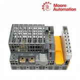
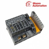
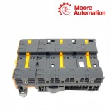
B&R X20CP1483 X20 Controller Module

B&R X20CP1483 X20 Controller Module Item NO.: 2940462

Write a Review
US$ 1.00
Quantity
Stock ( 28 )

Copy and share this link on social network or send it to your friends

Copy
Request Price & AvailabilitySend the part number and quantity. Our team will confirm stock, condition, lead time and the best quotation.
  • MOQ: 1 piece
  • International shipping
  • 1-year warranty on eligible items
  • Fast response during business hours
Product Name B&R X20CP1483 X20 Controller Module
Item NO. 2940462
Weight 0.1 kg = 0.2205 lb = 3.5274 oz
Category B&R
Brand B&R
Creation Time 2026-11-18

B&R X20CP1483 X20 Controller Module
B&R X20 System

B&R X20CP1483X20 Controller Module

100 MHz x86-compatible CPUCompactFlash application memoryPOWERLINK V1/V2X2X Link master
Configuration snapshot
Processorx86 100 compatible
Clock frequency100 MHz
Working memory32 MB SDRAM
01

Product Summary

B&R X20CP1483 is an X20 controller module for the B&R X20 control system. Installed at the head of an X20 station, X20CP1483 executes the Automation Runtime application, exchanges data with the local I/O chain and connects that control task to the controller’s external communication ports.

At startup, X20CP1483 reads the runtime and machine project from its removable CompactFlash card. The processor uses SDRAM for active program execution, while the SRAM area holds user data selected for retention, so application loading, live data and retained values are handled by separate memory resources.

Power for X20CP1483 enters through the X20TB12 terminal block and feeds both the CPU section and the local X2X Link path. Ethernet carries standard network traffic, POWERLINK serves the configured real-time network, X2X Link exchanges data with the local module chain, and the RS232 and USB connections remain separate service paths.

02

Specification Details

Specification X20CP1483
Product type X20 controller module
Processor x86 100 compatible
Clock frequency 100 MHz
Working memory 32 MB SDRAM
User RAM 128 kB SRAM
Remanent variables Maximum 32 kB
Application memory 1 CompactFlash slot; card ordered separately
Shortest task class 1 ms
Typical instruction cycle 0.09 µs
Interface expansion 1 X20 interface-module slot
Ethernet 10/100 Mbit/s, shielded RJ45, max. 100 m segment
POWERLINK V1/V2 managing or controlled node, 100 Mbit/s
RS232 Via X20TB12, max. 115.2 kbit/s, max. 900 m
USB 2 × USB 1.1 Type A, 0.5 A each
CPU / X2X supply 24 VDC −15% / +20%, max. 2.2 A
X2X output 7 W nominal; parallel and redundant operation supported
Power consumption 6 W without memory card, interface module and USB
Environment −25 to 60°C horizontal; −25 to 50°C vertical; IP20
Mechanical 150 × 99 × 85 mm; approx. 300 g; fanless
03

Configuration and Programming

X20CP1483 separates the boot image, active runtime data and retained variables, so each resource has a different role during project transfer and startup diagnosis.

01

Boot image path

Automation Runtime and the machine project are read from CompactFlash during startup. CPU supply indication therefore confirms electrical power only; the controller still needs readable media containing the correct runtime and project for the configured hardware.

02

Retained-data handling

Battery-backed SRAM carries user data that must remain available across a normal power interruption. The project decides which variables are remanent, while the battery indication identifies whether the retention circuit needs attention.

03

Hardware configuration match

The project hardware tree must agree with the installed interface module and the X20 station layout. A valid CompactFlash image can still stop before normal operation when the physical module selection or slot assignment differs from the saved configuration.

04

Communication and Connectivity

X20CP1483 provides separate engineering, real-time network, local I/O and serial service paths; diagnosing them independently prevents one healthy link from masking another failed path.

01

Ethernet and POWERLINK roles

Standard Ethernet carries engineering or ordinary network traffic, while POWERLINK operates in its configured managing-node or controlled-node role. Link indication and node configuration must be checked on the interface that is actually failing.

02

Local X2X path

X2X Link transfers data to the local X20 module chain through the controller power section. Loss of local I/O therefore directs attention to X2X supply, module seating and the first downstream position rather than to the Ethernet cable.

03

Serial and local service access

RS232 reaches the controller through X20TB12, and the USB ports provide local service connections. Terminal wiring, baud settings and the selected interface module remain separate configuration items even though they are mounted on the same controller.

05

Questions & Answers

01FAQ

What must be moved before an X20CP1483 replacement can start?

Before replacing X20CP1483, identify the installed CompactFlash card, back up the project, record the interface-module type and label the X20TB12 wiring so application media and connections return to the same positions.

02FAQ

Why can an X20CP1483 power up but fail to run the machine project?

X20CP1483 can show supply status without a usable application if the CompactFlash card is absent, unreadable or contains the wrong Automation Runtime project; check the CF indication and card contents first.

03FAQ

How should X20CP1483 Ethernet and POWERLINK faults be separated?

On X20CP1483, inspect the dedicated Ethernet and POWERLINK LEDs independently, confirm the configured POWERLINK node role, and verify the correct RJ45 network is connected before changing software settings.

04FAQ

What should be checked when X20CP1483 loses local I/O communication?

For X20CP1483, check the CPU/X2X supply, the X2X output path, module seating and the first downstream X20 station; local I/O loss is not diagnosed from the Ethernet link alone.

05FAQ

Why can X20CP1483 RS232 remain inactive after a CPU replacement?

For X20CP1483, confirm the X20TB12 conductor positions, serial parameters and application port assignment; a running Ethernet connection does not validate the separate RS232 path.

06FAQ

Why does an X20CP1483 project reject the installed interface module?

X20CP1483 compares the configured hardware with the module fitted in its expansion slot, so verify the exact interface-module order number, slot seating and project hardware tree before changing network settings.

06

About Moore Automation

Moore Automation

https://www.mvme.cn/

Moore Automation supplies industrial control hardware across PLC, DCS, motion, monitoring and distributed I/O product groups. Each enquiry is kept against the full model, suffix, revision, requested condition and quantity.

Multi-brand automation scope
Full-model identification
Current and legacy hardware
One recorded enquiry
FOCUS 01

Automation scope

Controller, I/O, communication, drive and monitoring requirements are separated before sourcing.

FOCUS 02

Part identity

Nameplate details and the complete order string stay attached to the request.

FOCUS 03

Commercial record

Condition, quantity, availability and shipment terms are returned against the same item identity.

Contact DetailsMoore Automation

CompanyMoore Automation
ManagerLeonia

No related record found

You May Also Like

Copyright © 2004–2026 www.mvme.cn. All rights reserved.

Disclaimer: Moore Automation Limited is an independent reseller and is not an authorized distributor or representative of the manufacturers featured on this website. Product names and trademarks belong to their respective owners.